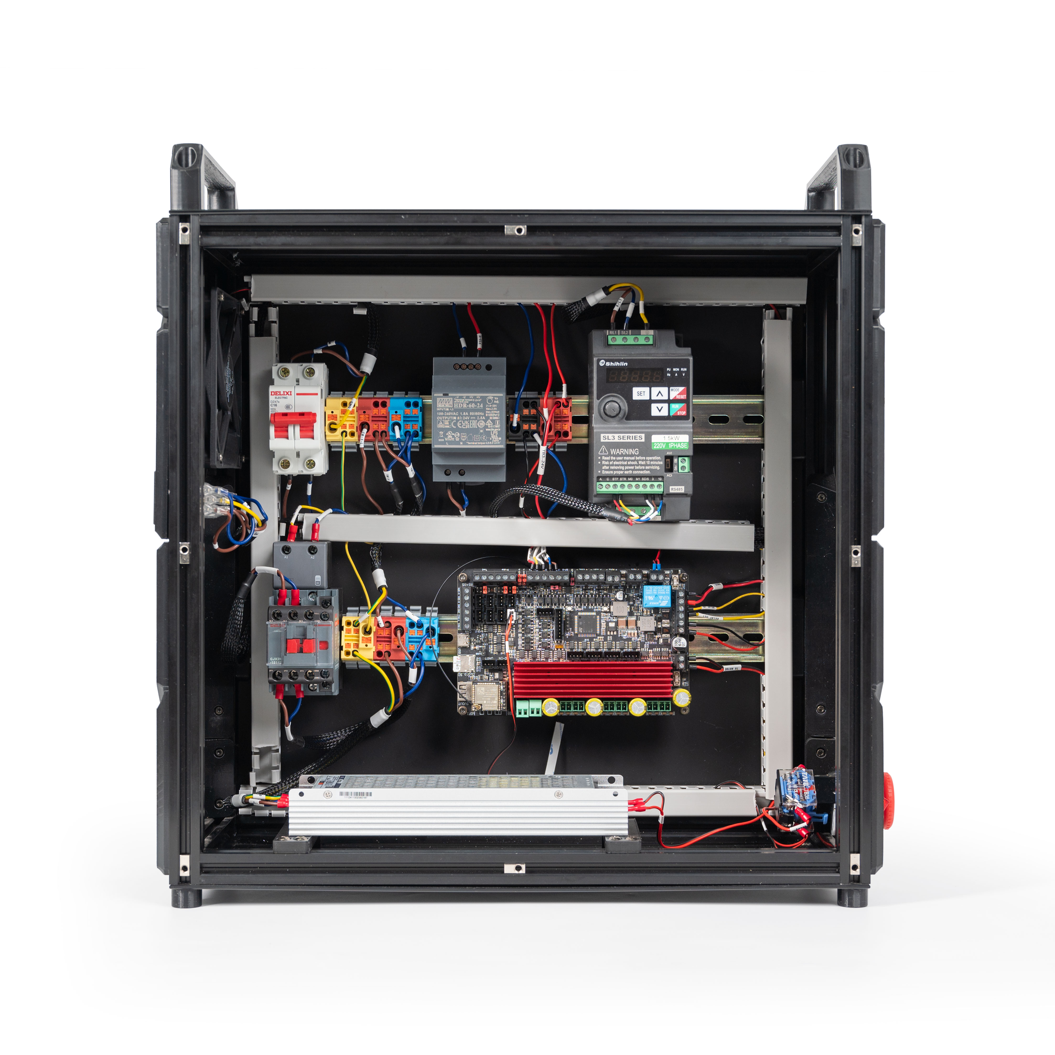
For Milo V2.0 build, please refer to the official manual.
For Universal Electronics Box build, please refer to the official manual.
This guide contains directions for a Universal Electronics Box Kit using the pre-cut, pre-terminated cables included in the kit. Important! Mains wiring should only be performed by certified personnel trained in local regulations and safety standards.
Attention: The power supply model included in the shipped kits has been changed to Meanwell HDR-60-24. Please note that the power supply shown in this guide is still the previous model; however, this does not affect the wiring.
¶ Preparation
¶ PSU
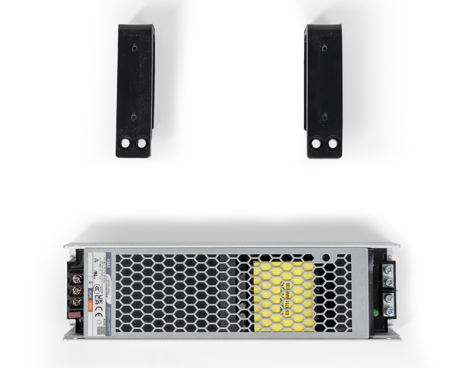
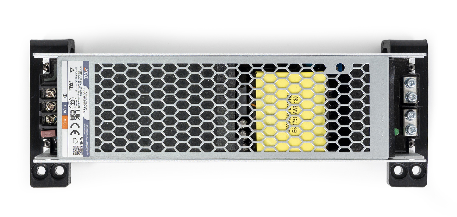
Position the power supply onto the printed part and align the holes. Secure with M3x10 SHCS screws. The screws are tapped directly into the printed part.
¶ Mainboard
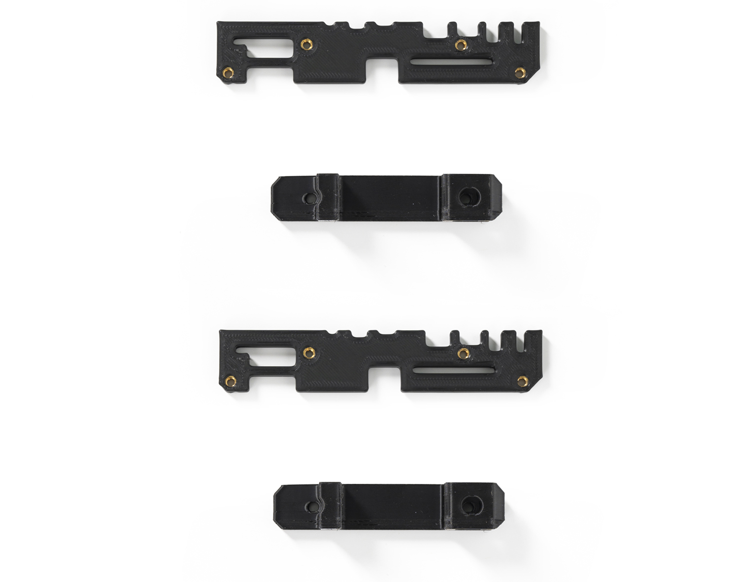
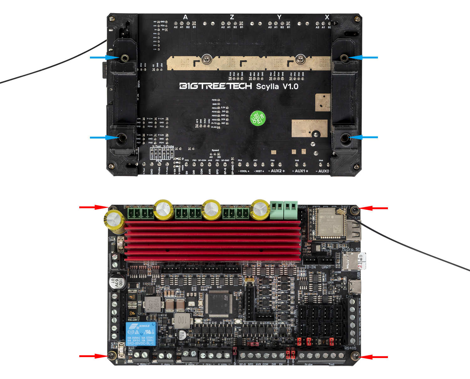
Position the printed parts as shown in the picture. Secure with M3x10 SHCS screws. The screws are tapped directly into the printed part.
¶ Below Deck Wiring
¶ General Placement
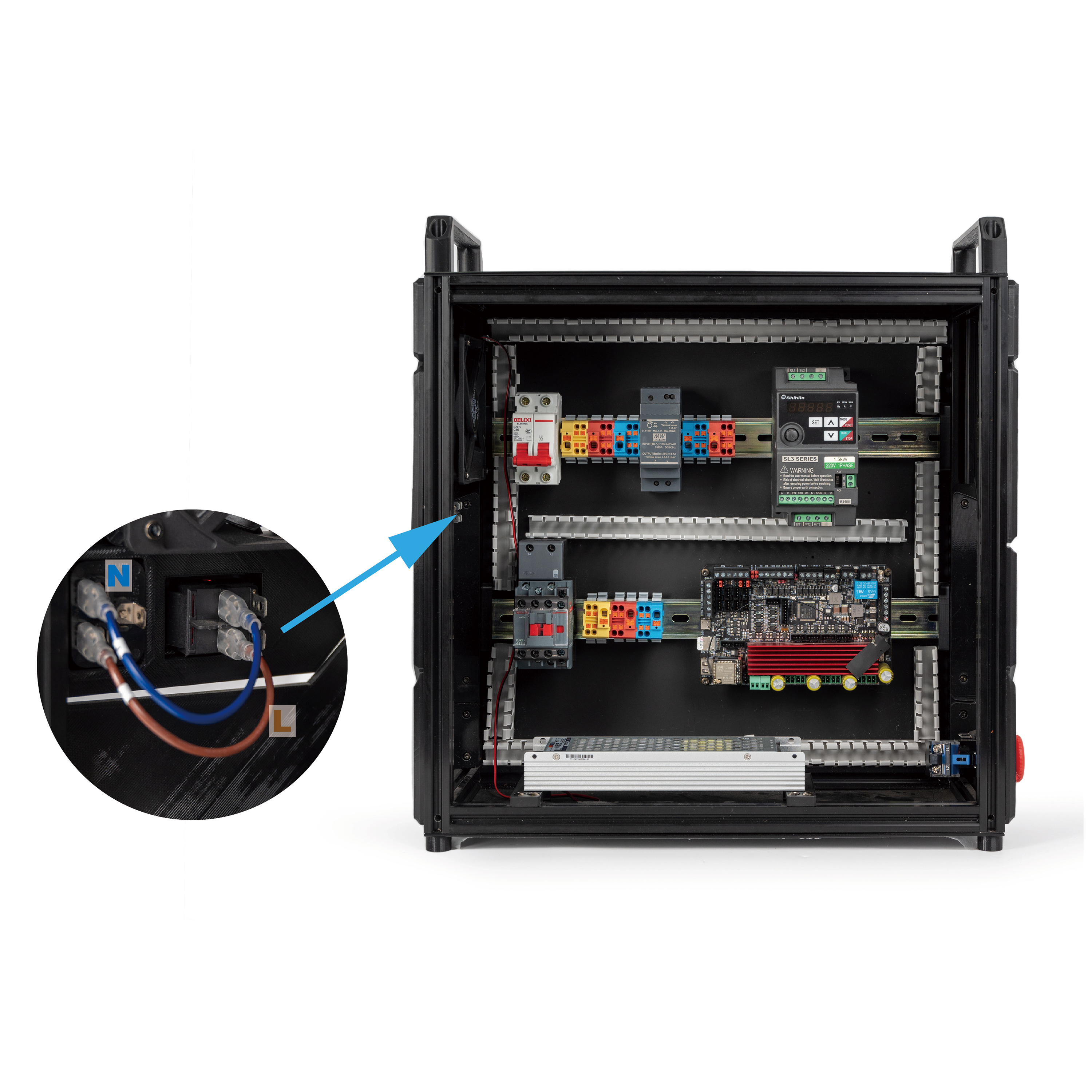
In this step, please prepare the inlet and place the electronic components as shown in the picture below.
¶ Connecting Inlet
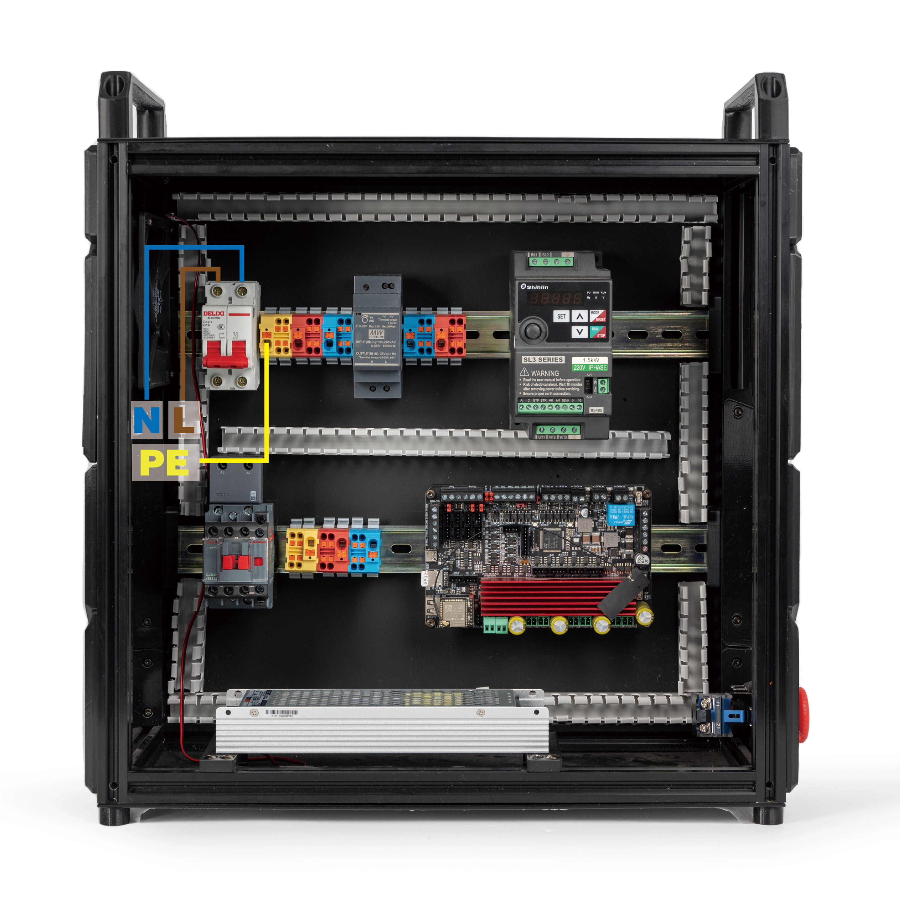
In this step we will connect the Inlet, Circuit Breaker and yellow terminal. Follow the following diagram:
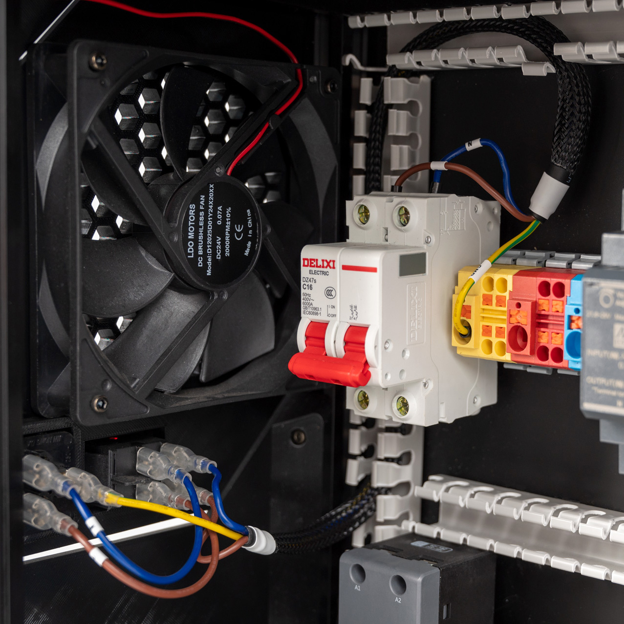
The end result should look like this:
¶ Connecting Circuit Breaker and Terminals
In this step we will connect the Circuit Breaker and Terminals. Follow the following diagram:
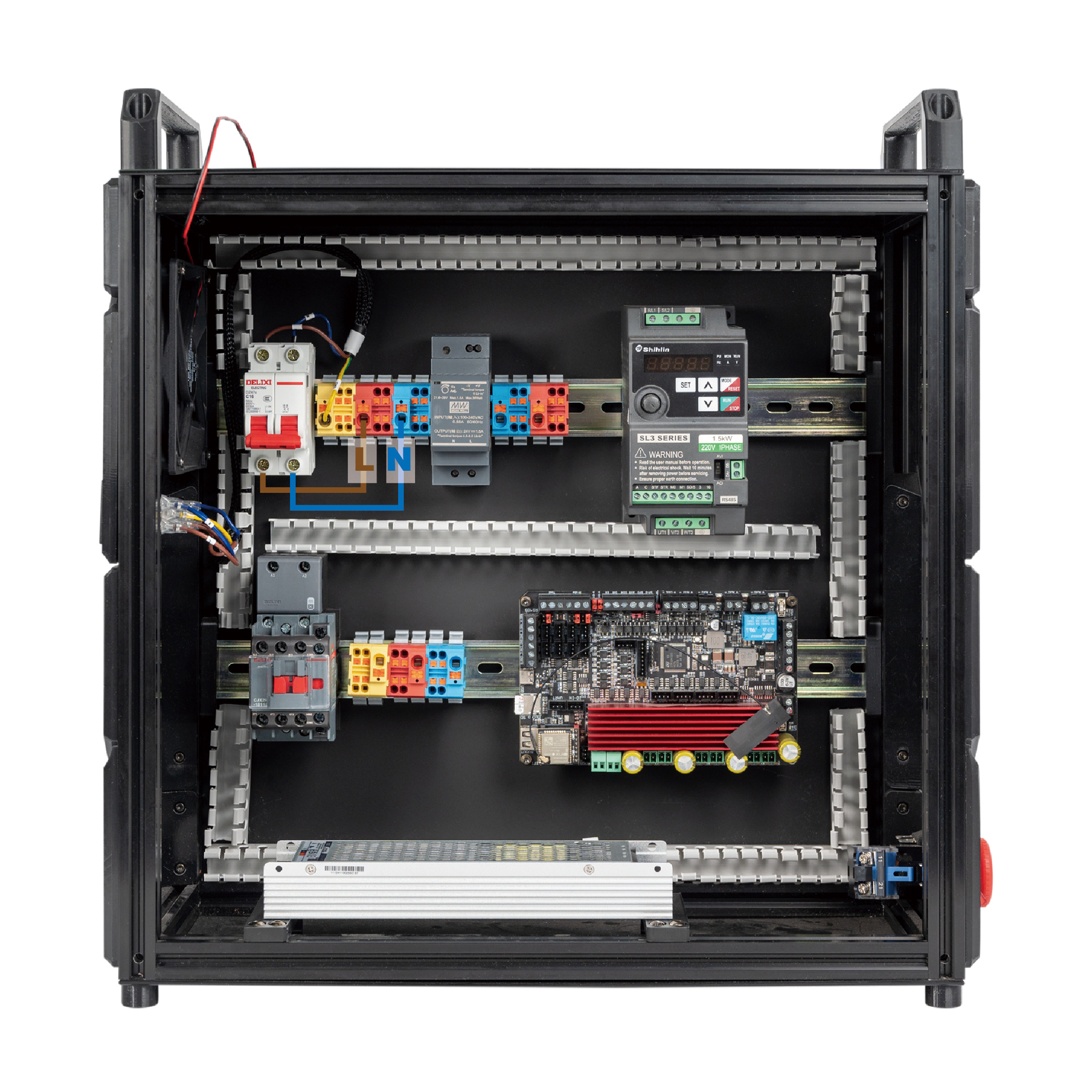
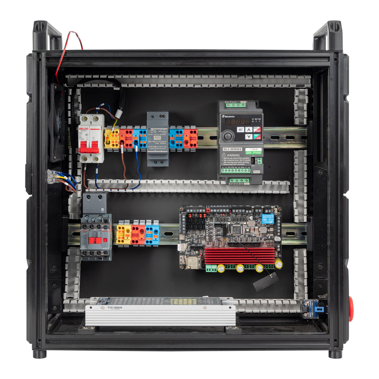
The end result should look like the following:
¶ Connecting Contactor and Terminals
In this step, we will connect the Contactor and Terminals. Follow the following diagram:
- Use the cable that is labeled TB-1 and CONTACTOR.
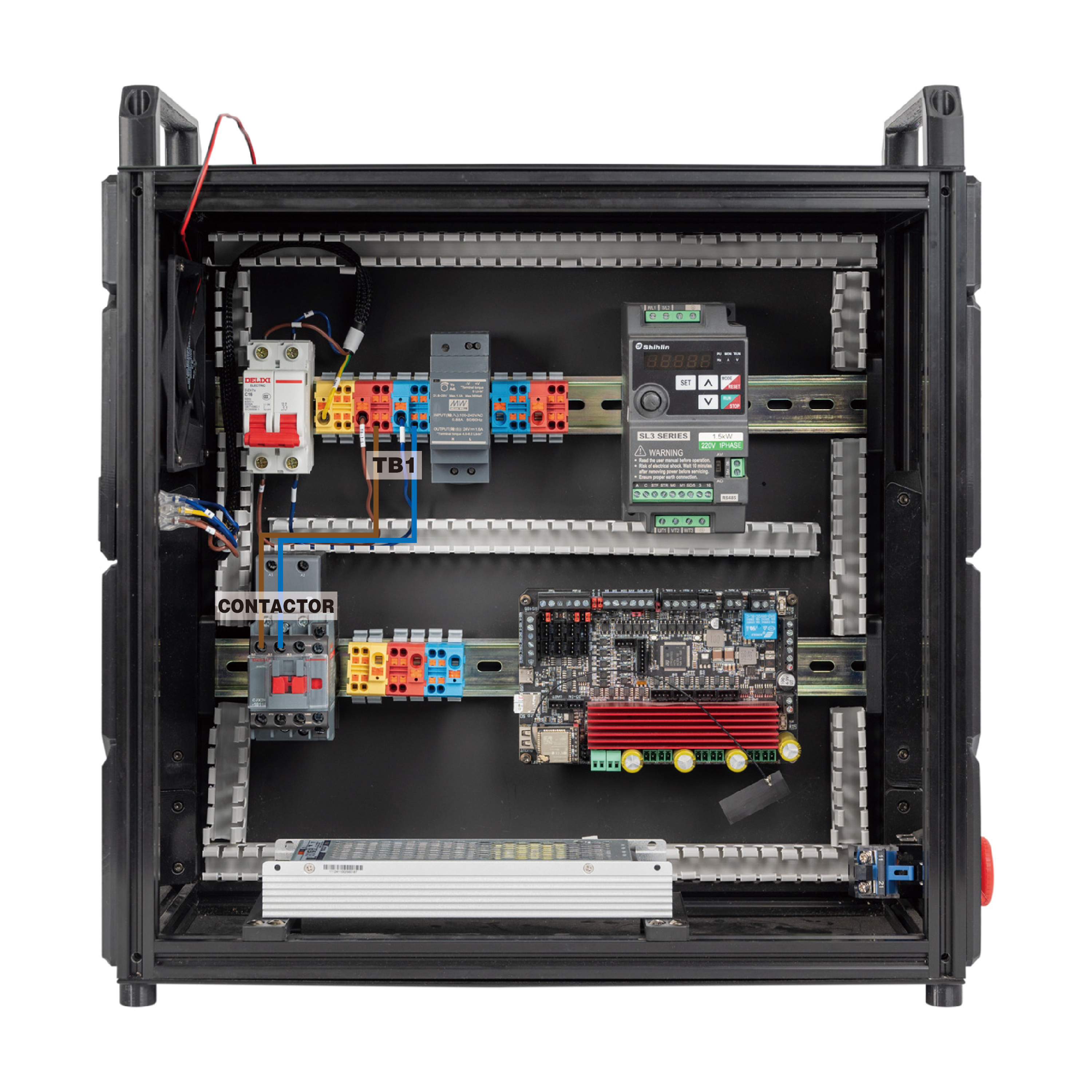
The overall result:
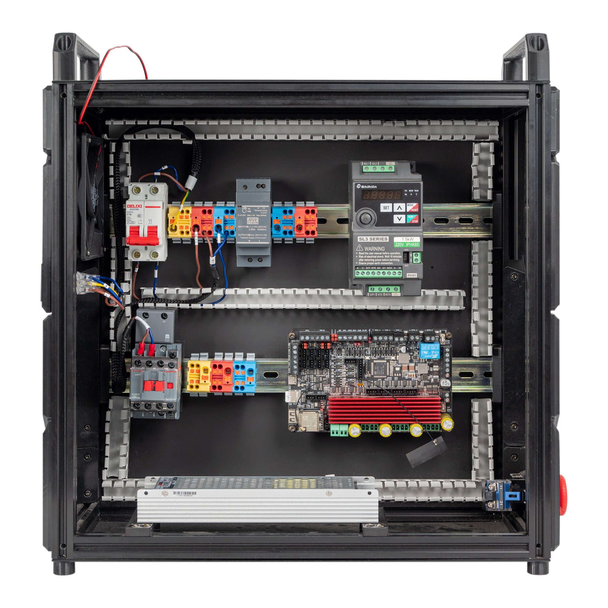
- Use the cable that is labeled TB-2 and CONTACTOR.
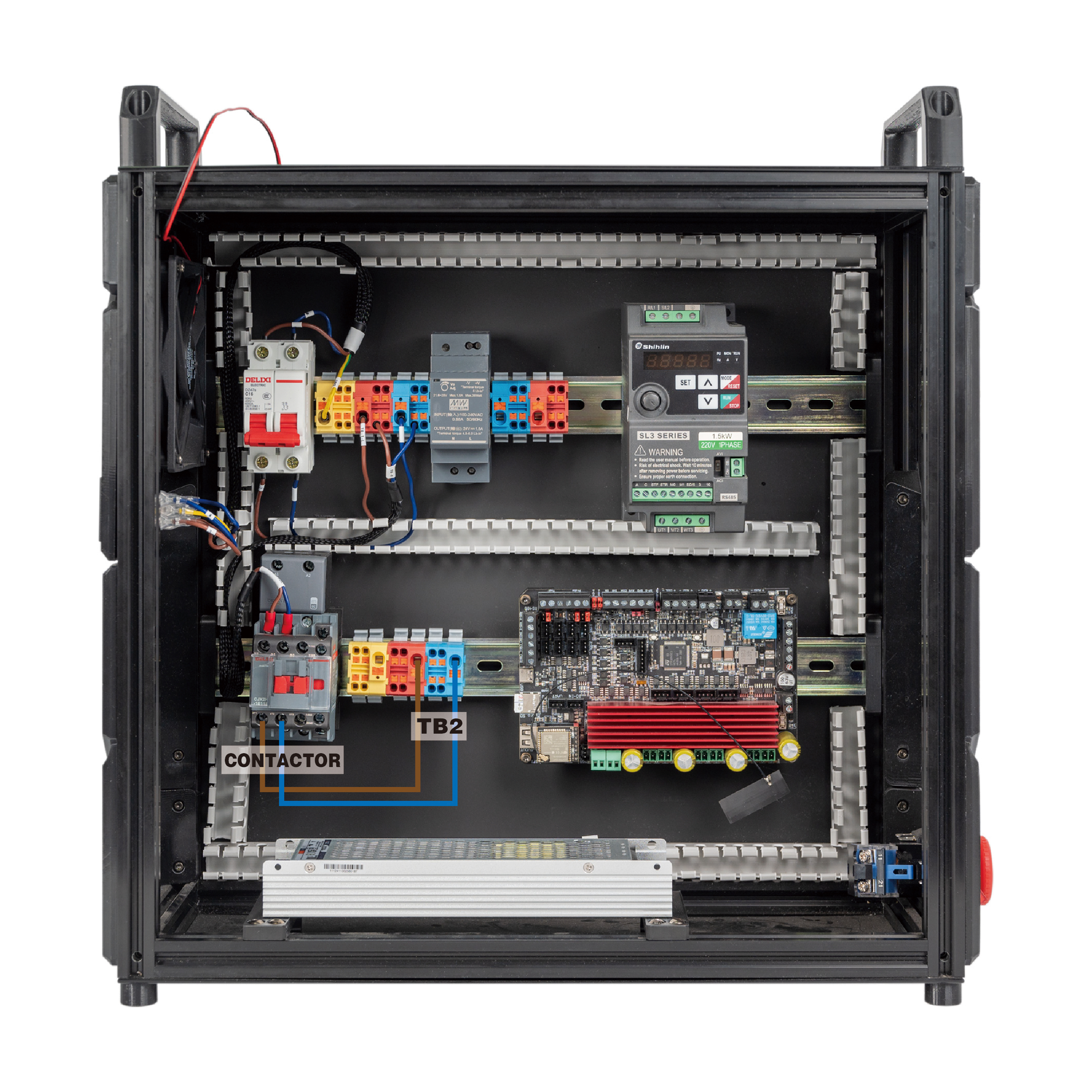
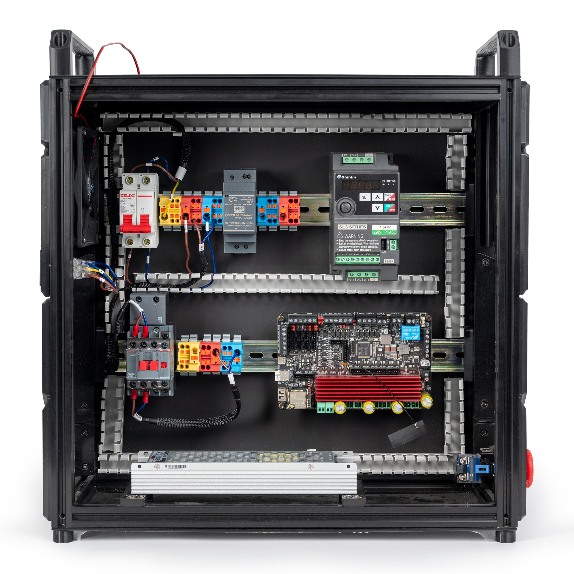
The overall result:
¶ Connecting the PSU
In this step, we will connect 30w PSU and terminals. Follow the following diagram:
- Use the cable that is labeled TB-1 and 24V L-N.
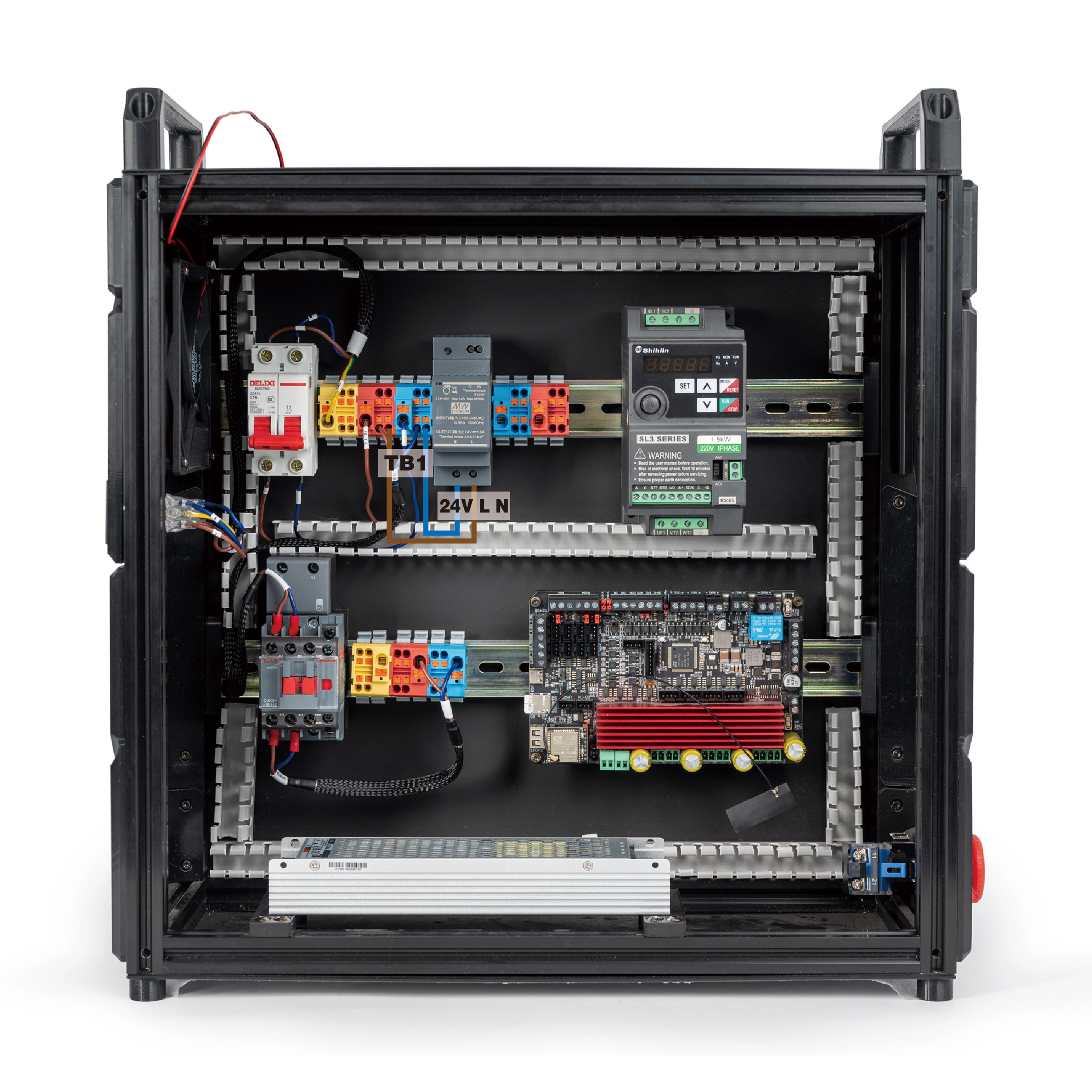
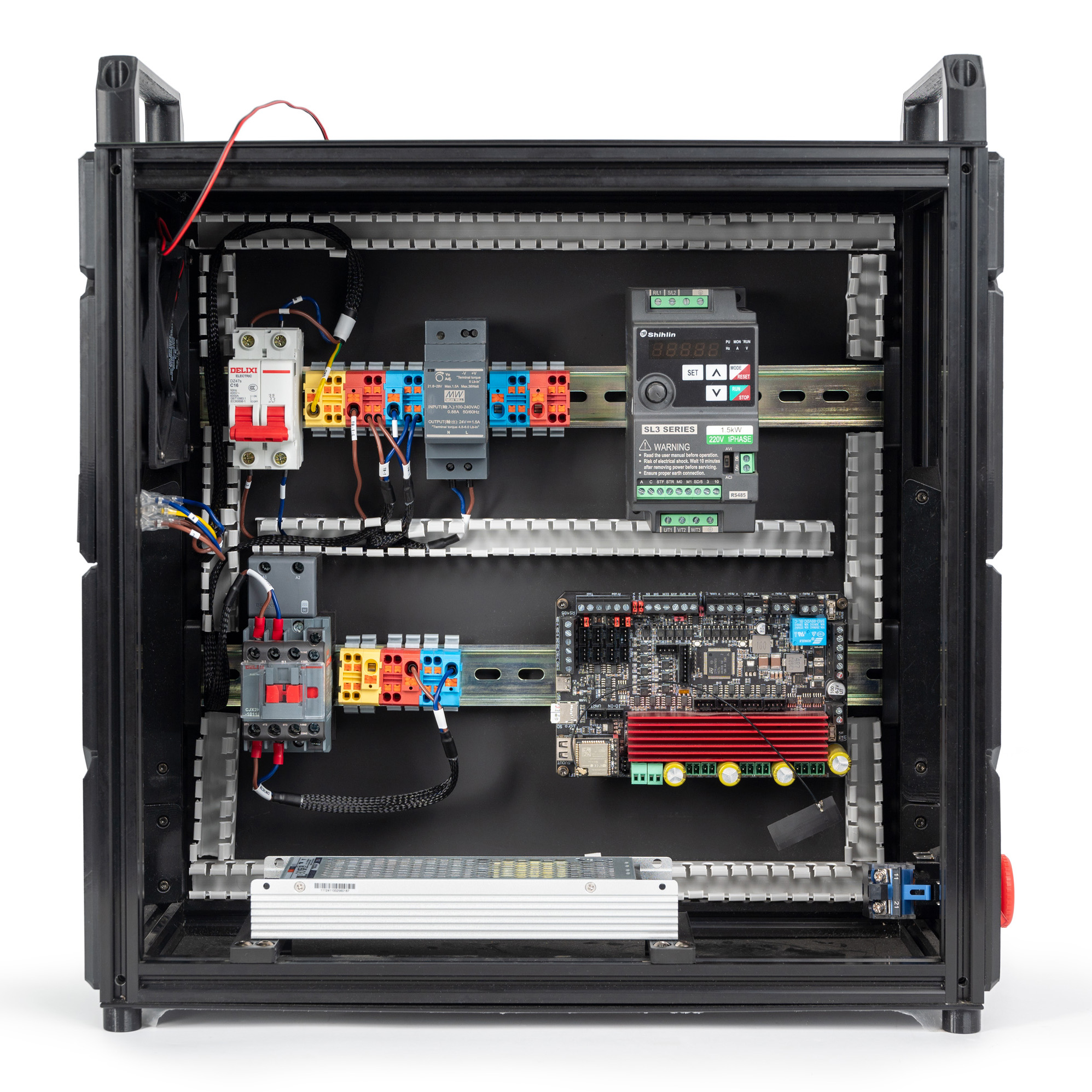
The overall result:
For the HDR-60-24 power supply, please follow this diagram:
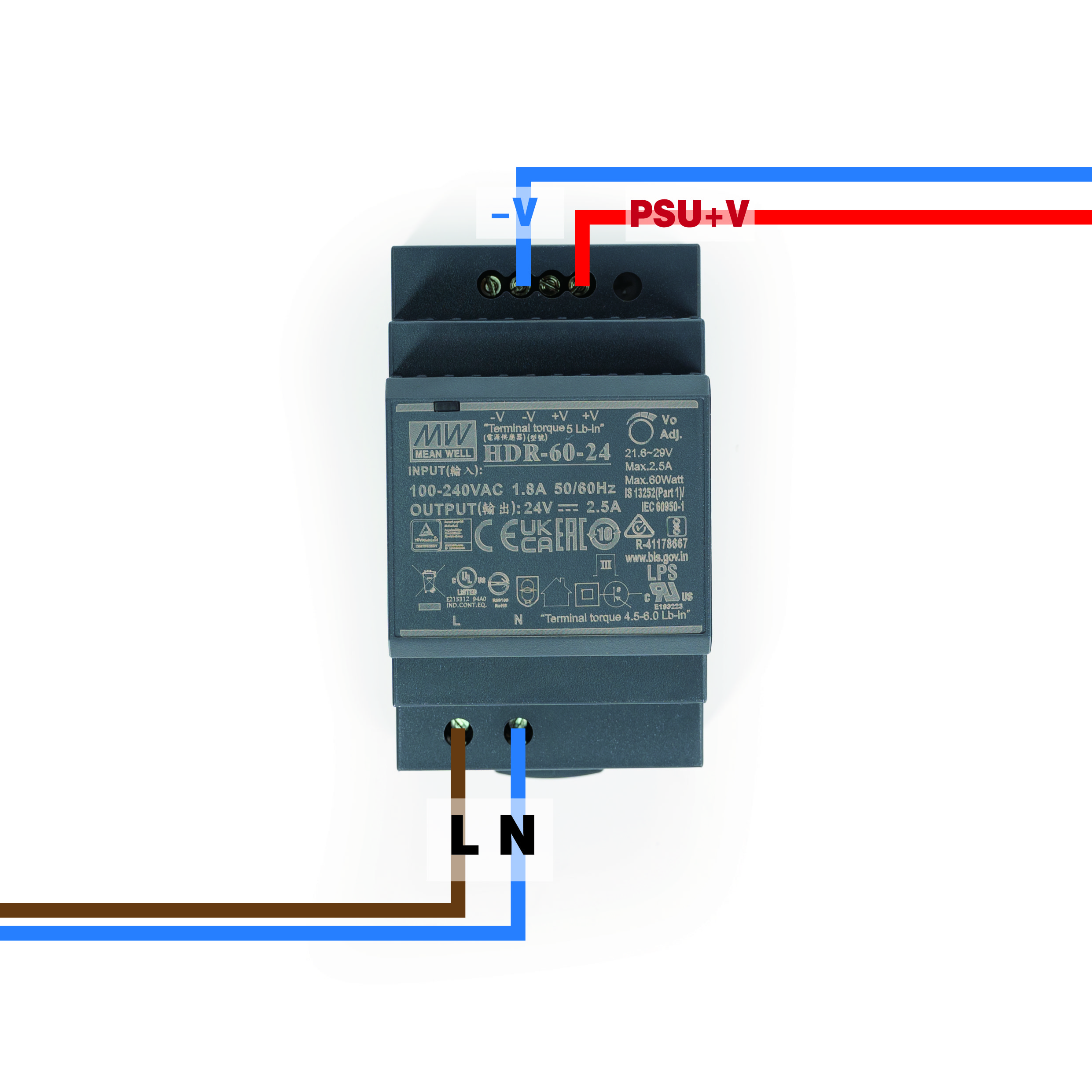
- Use the cable that is labeled PSU+V and 24V and the cable that is labeled -V and COM.
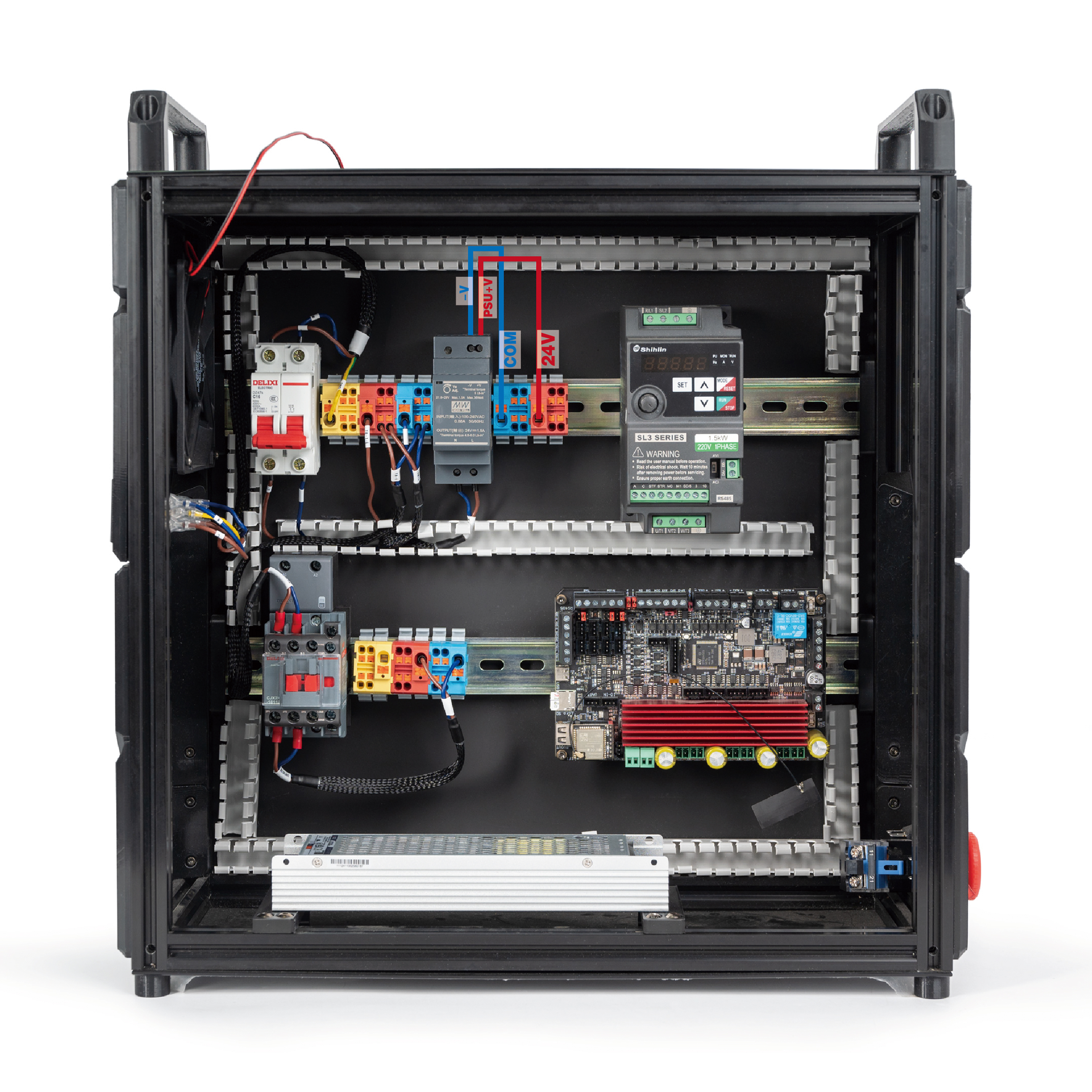
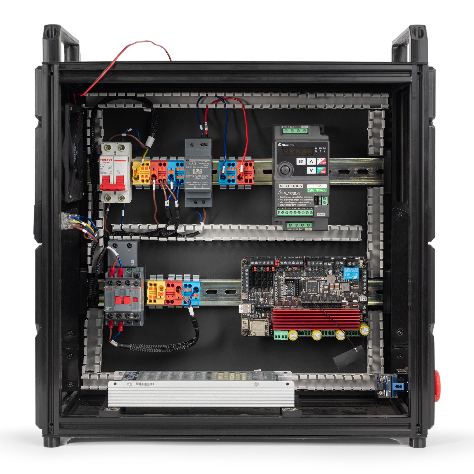
The overall result:
¶ Connecting the GND Cable
In this step, we will connect TB1 To TB2 GND cable. Follow the following diagram:
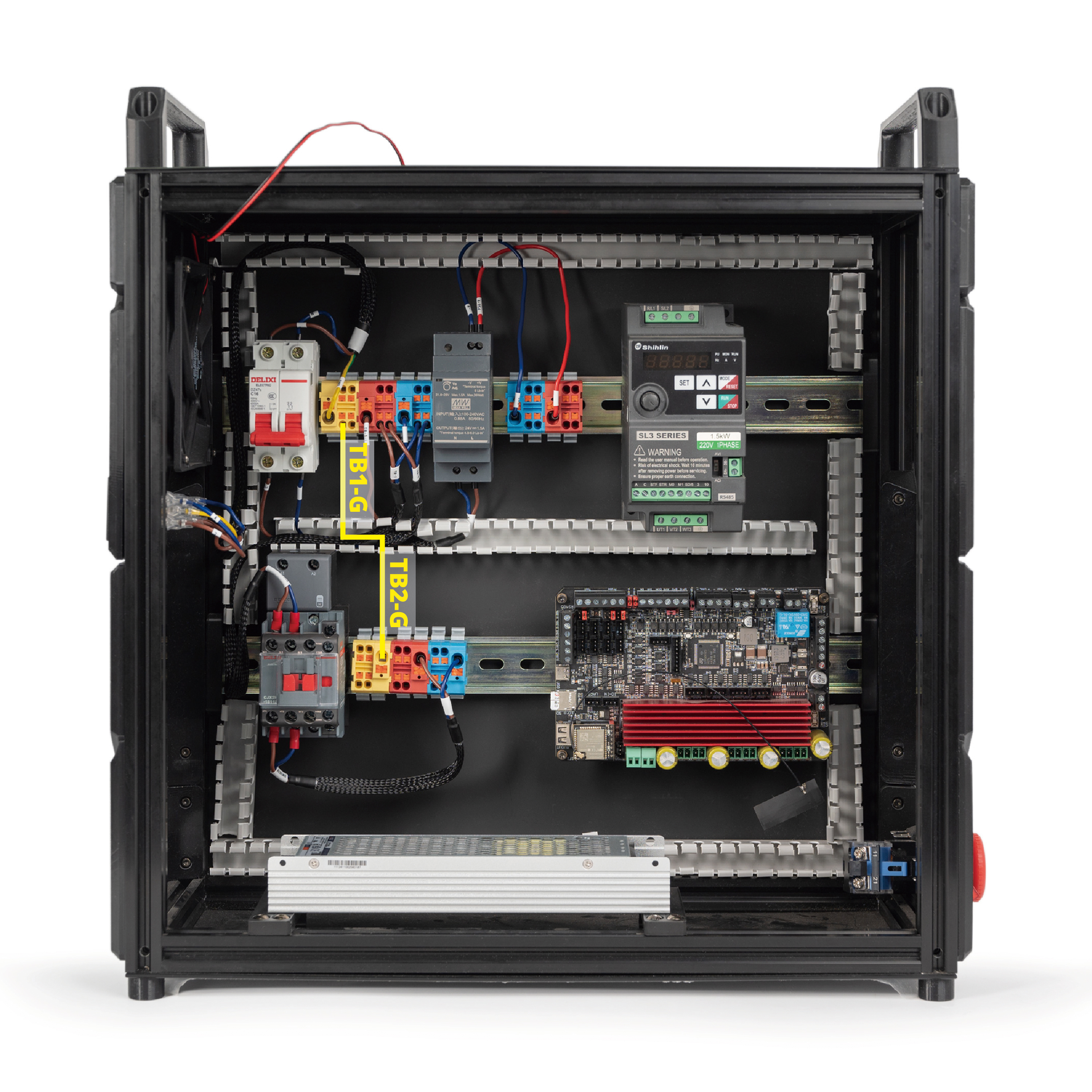
The overall result:
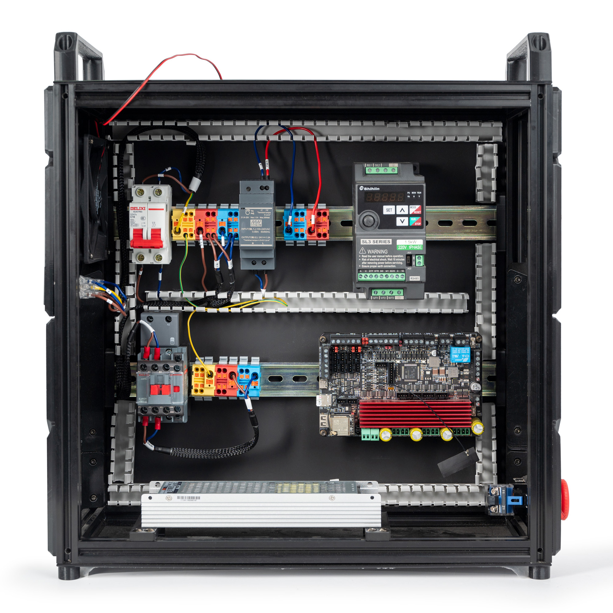
¶ Connecting the VFD and Terminals
In this step, we will VFD and terminals. Use the cable that is labelled TB-2 and TO VFD. Follow the following diagram:
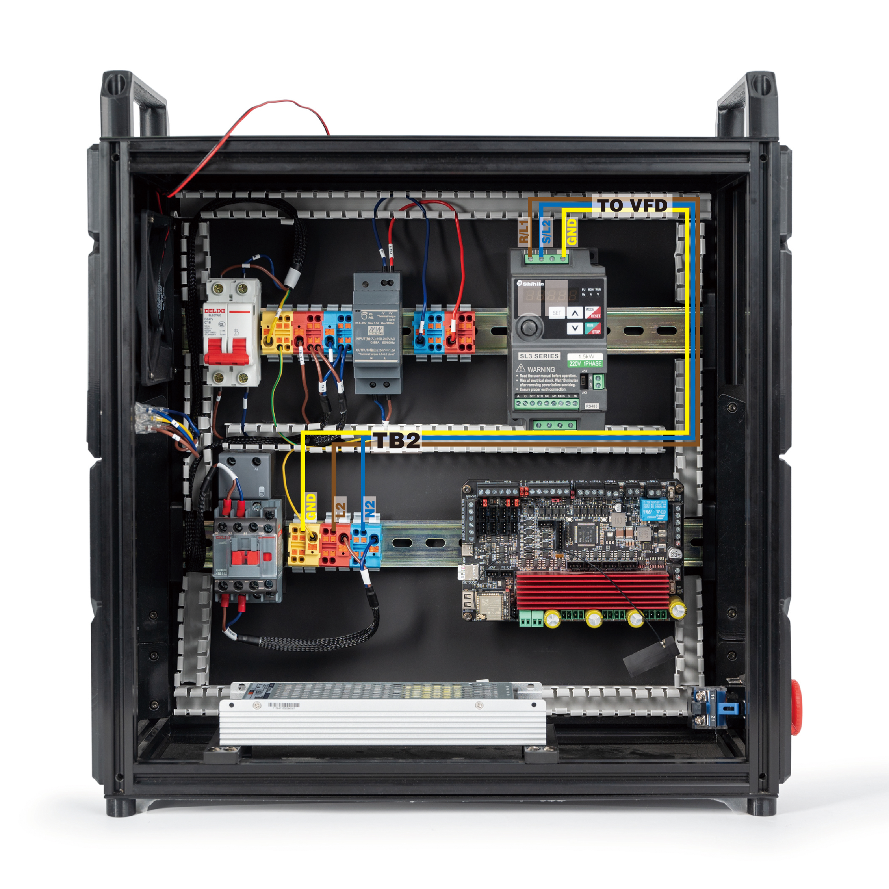
The result is below:
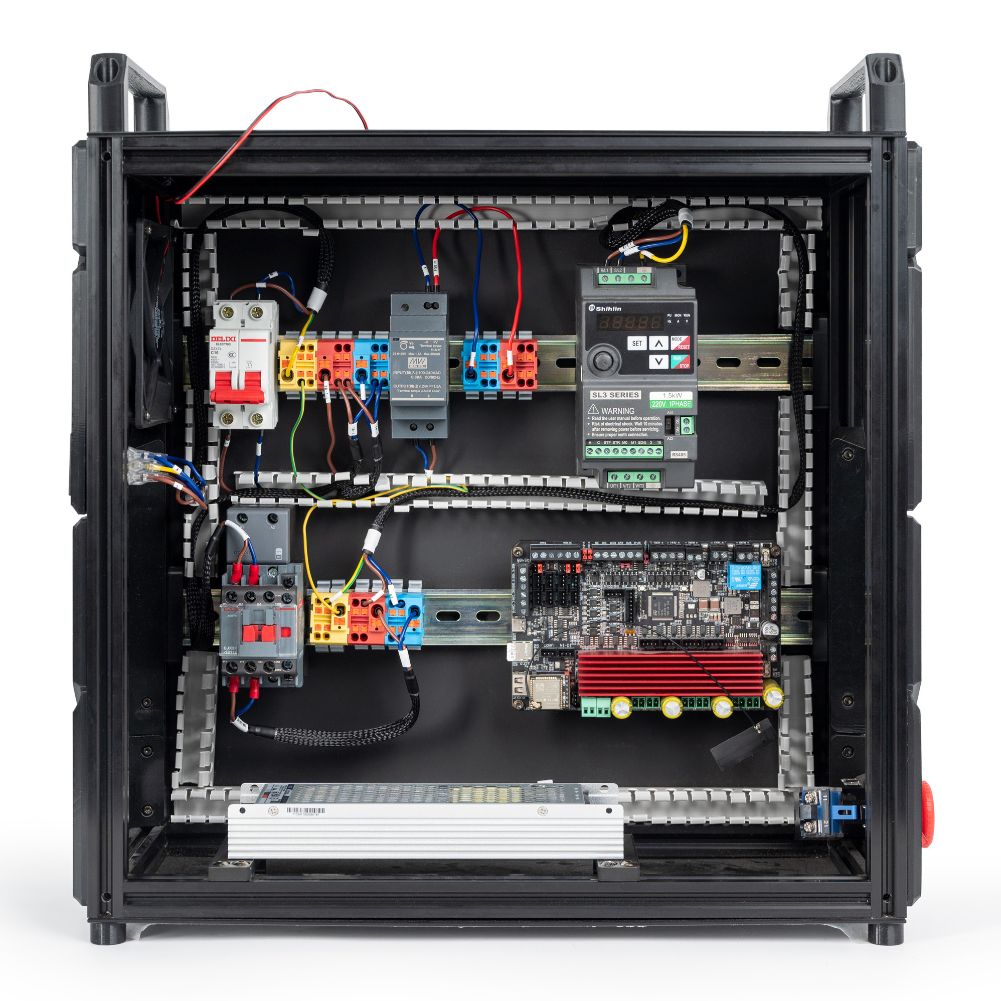
If you use a 110V VFD, please follow below picture.
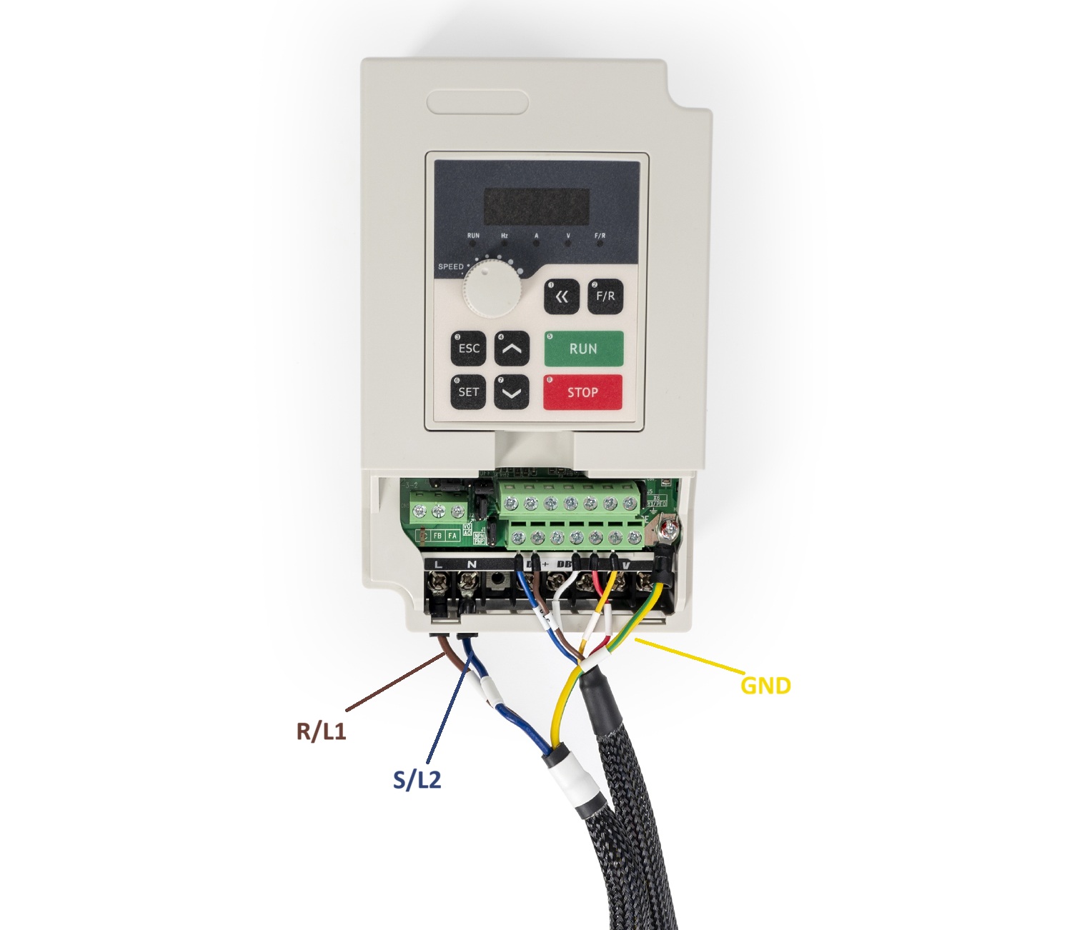
Note: The cable included in the kit is designed for 220V VFD. Please re-crimp L/N cable as needed.
¶ Connecting the PSU, Mainboard and Terminals
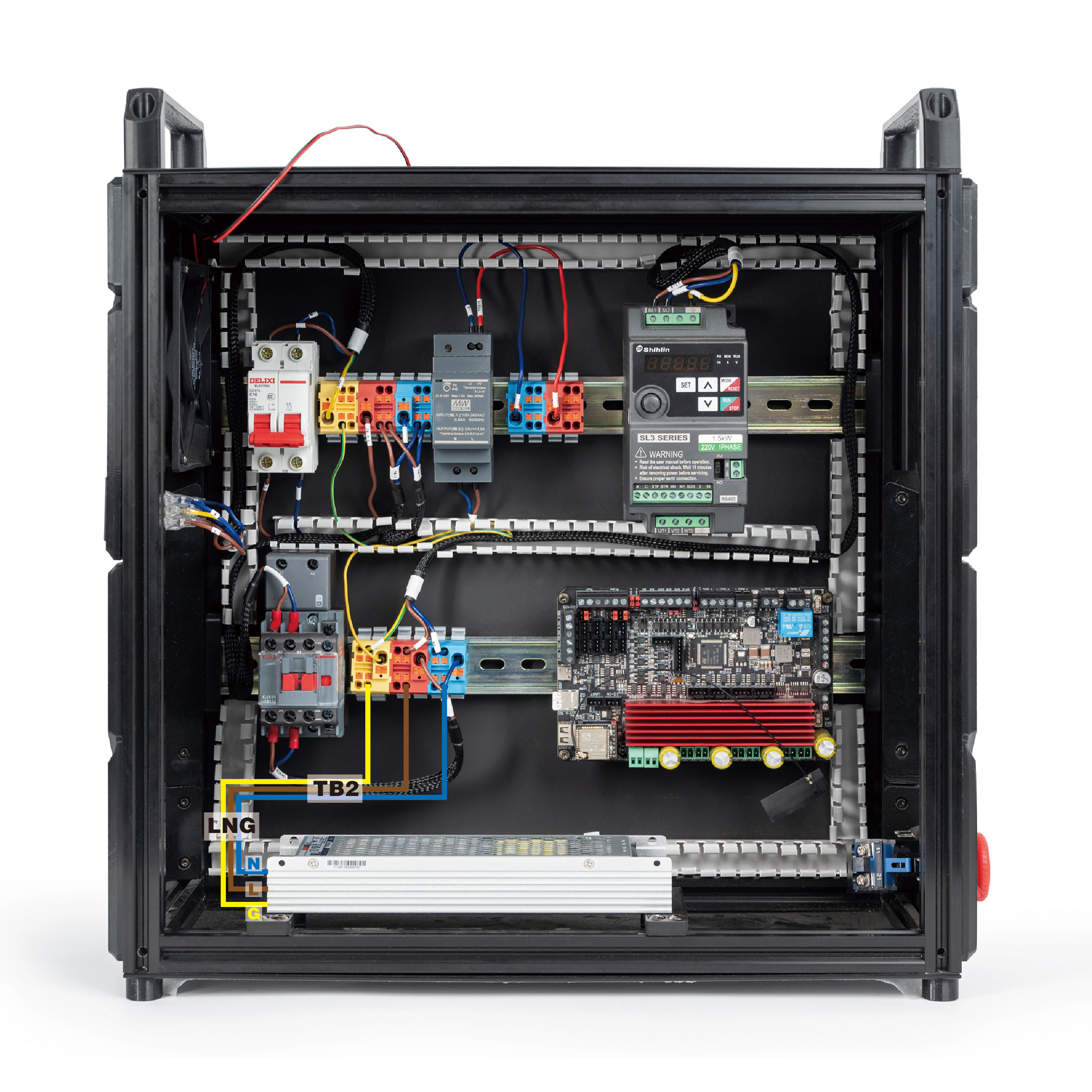
In this step, we will the power supply. Follow the diagram:
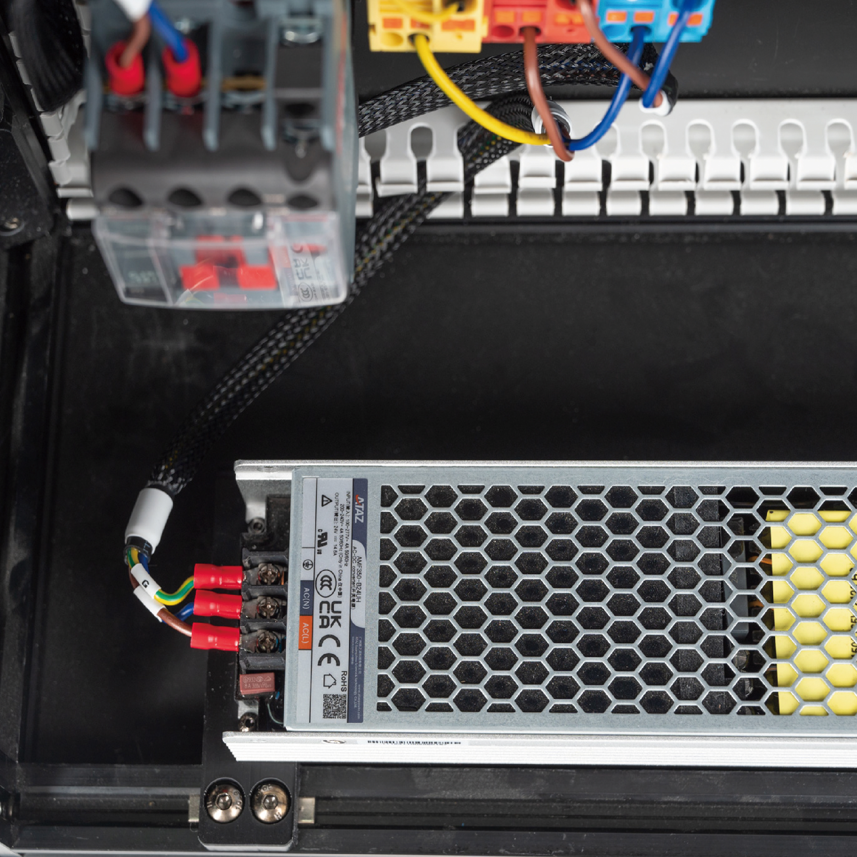
- Connect the PSU and terminals using the cable labelled LNG and TB-2.
Here is the result:
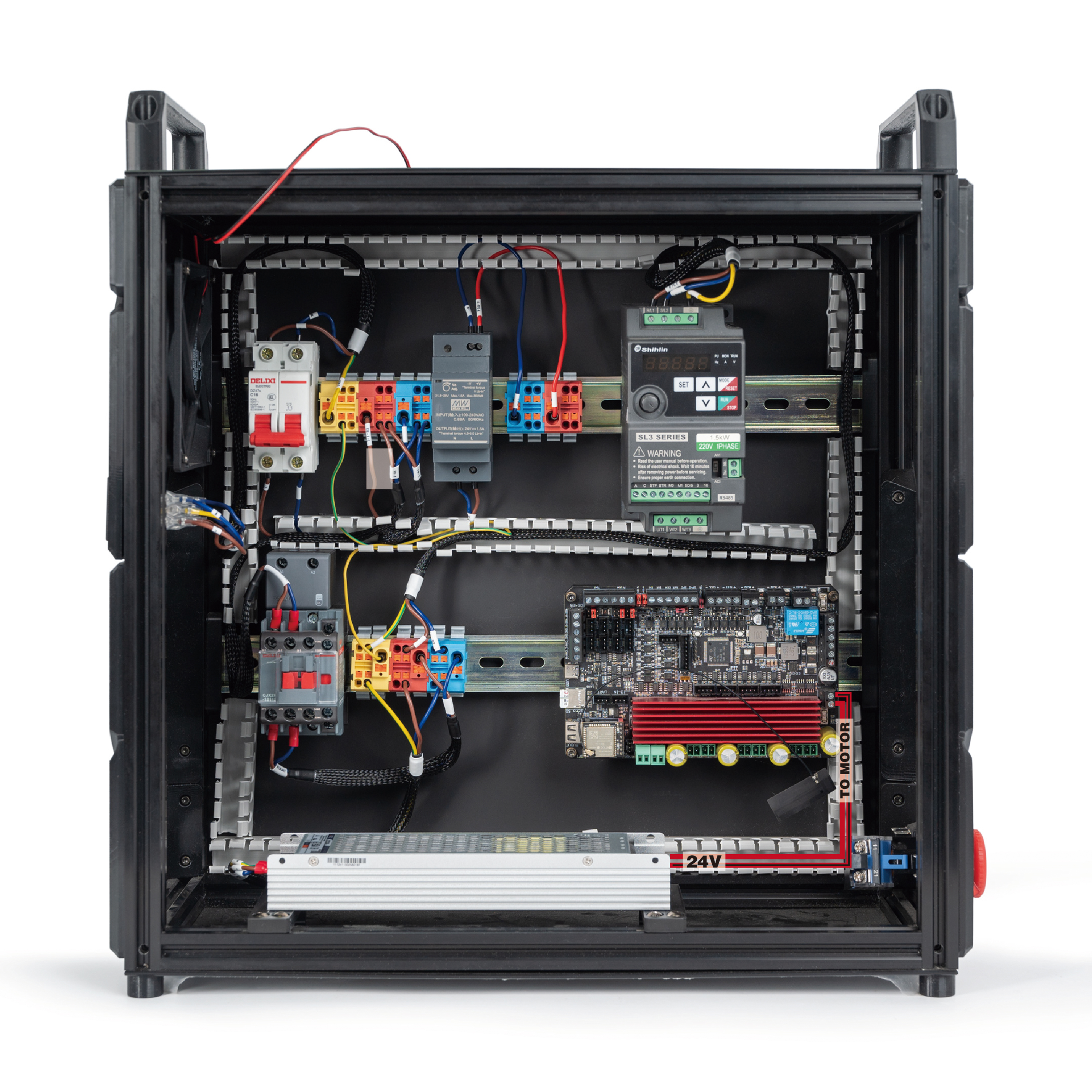
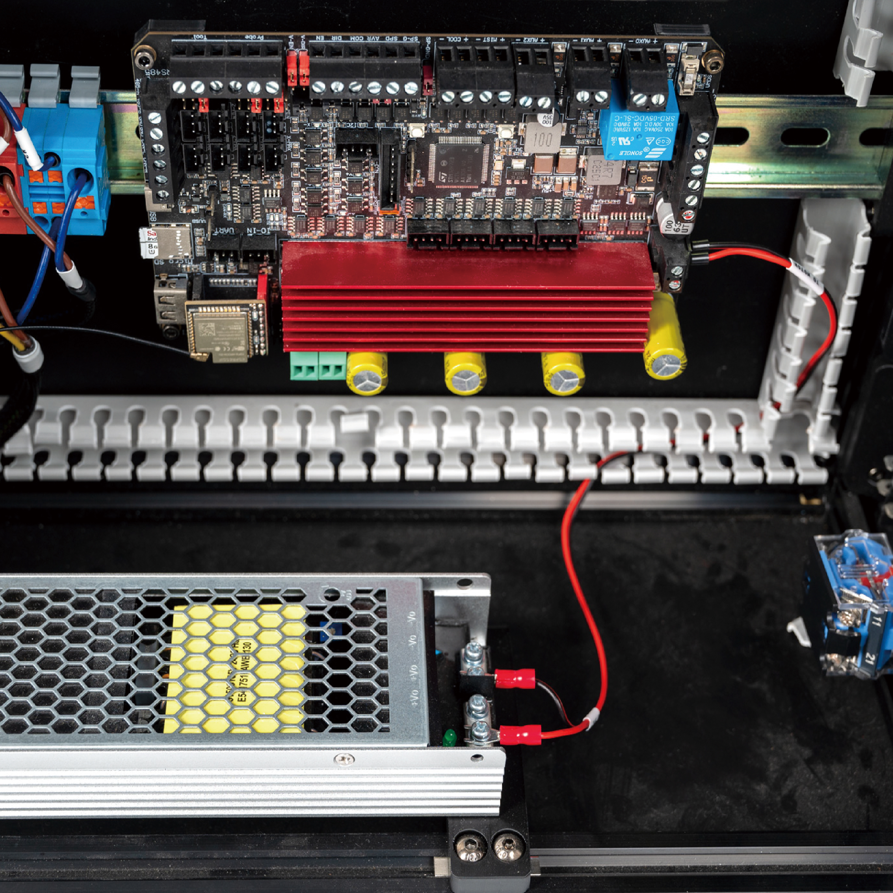
- Connect PSU and Mainboard using the cable labelled 24V and TO MOTOR.
Here is the result:
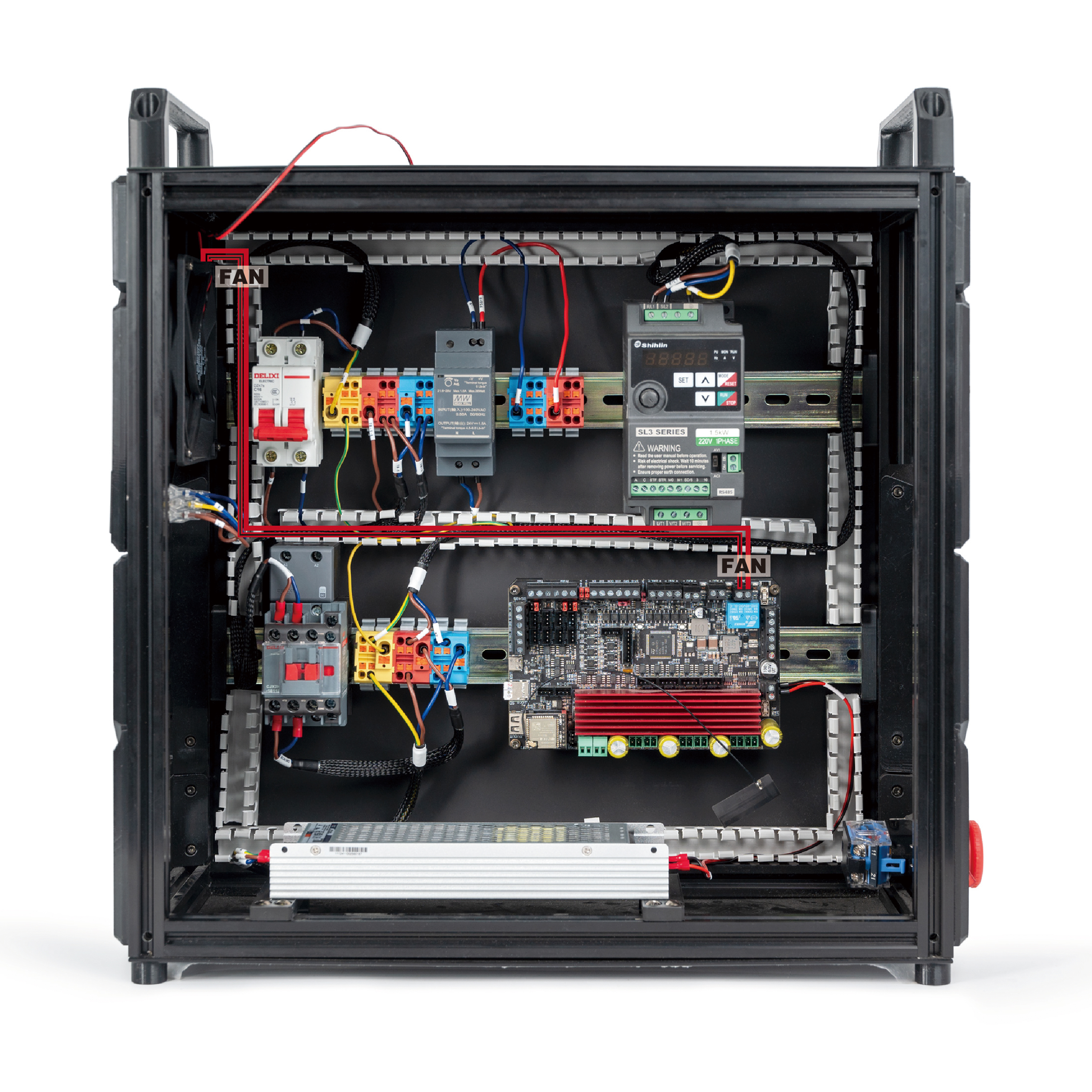
¶ Connecting the Fan
In this step, we will connect the fan. Follow the following diagram:
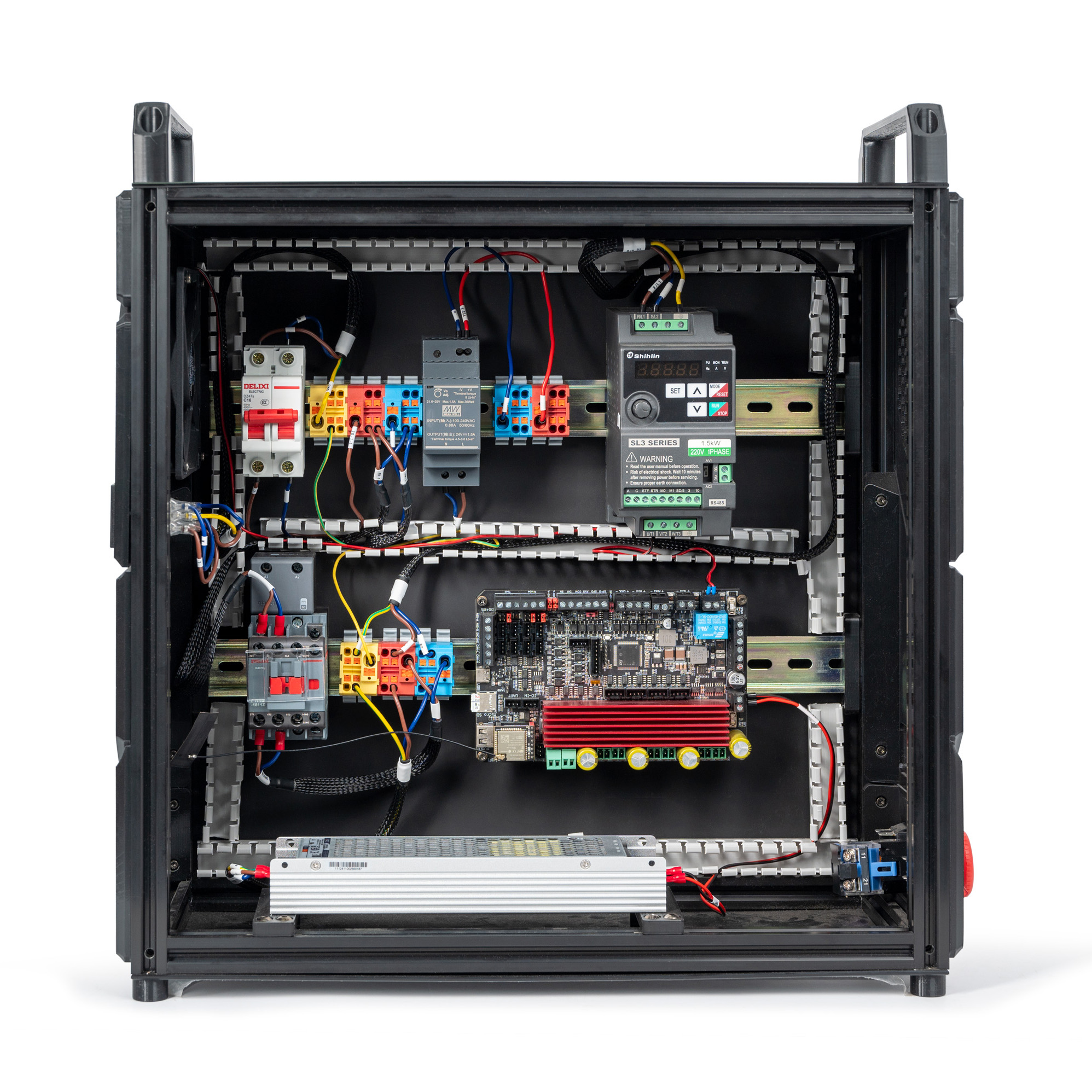
The result:
¶ Connecting the Mainboard
Use the cable that is labeled MCU 24V and 24V.
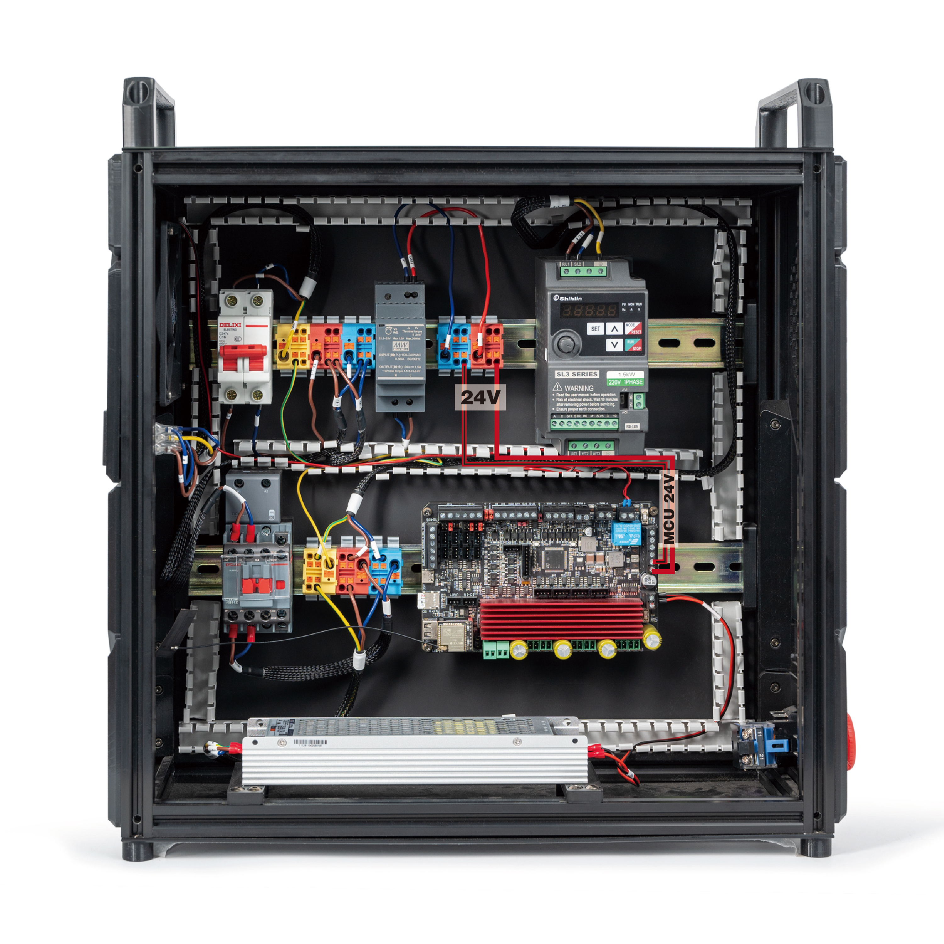
The result:

¶ Connecting the E-stop
In this step, we will connect the E-stop.
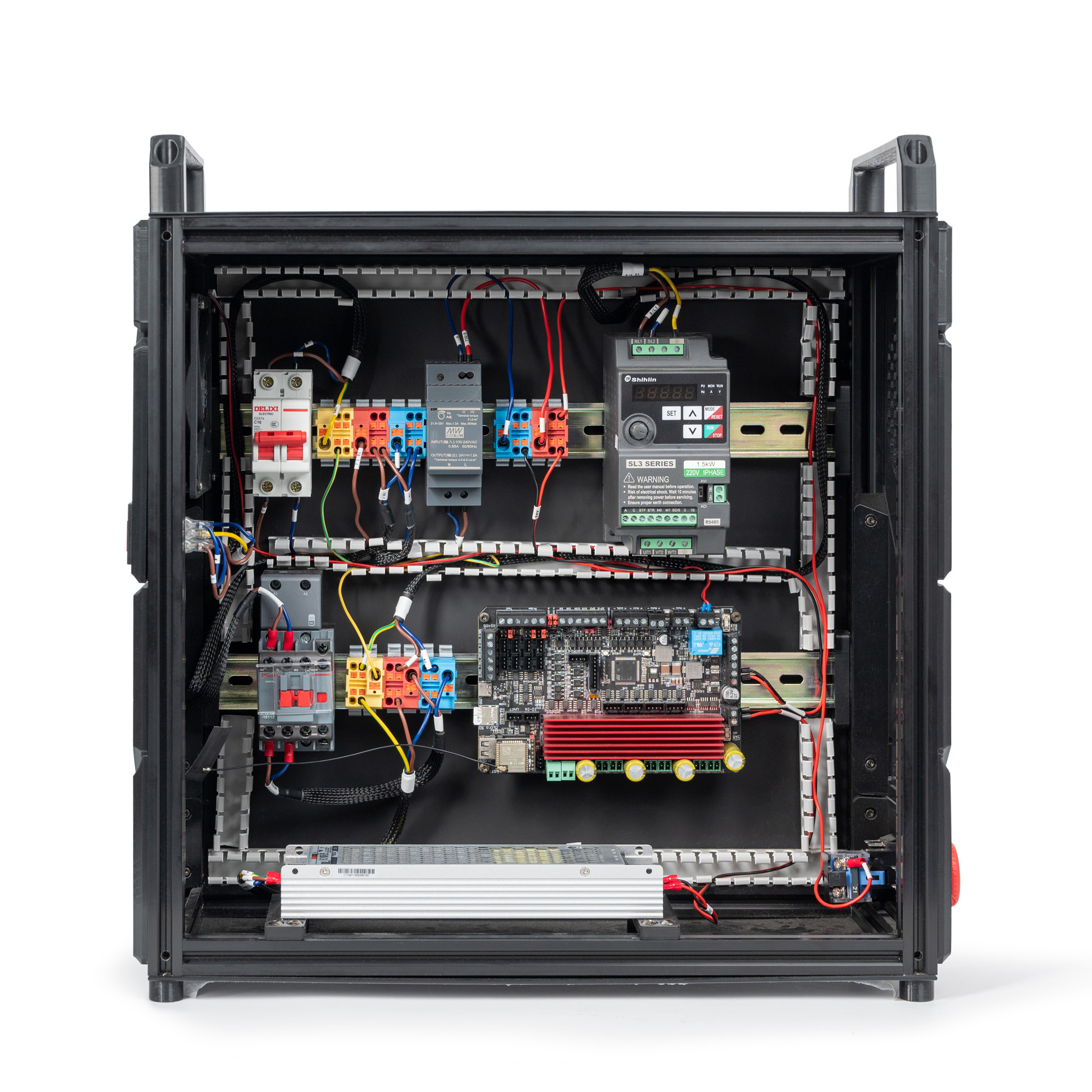
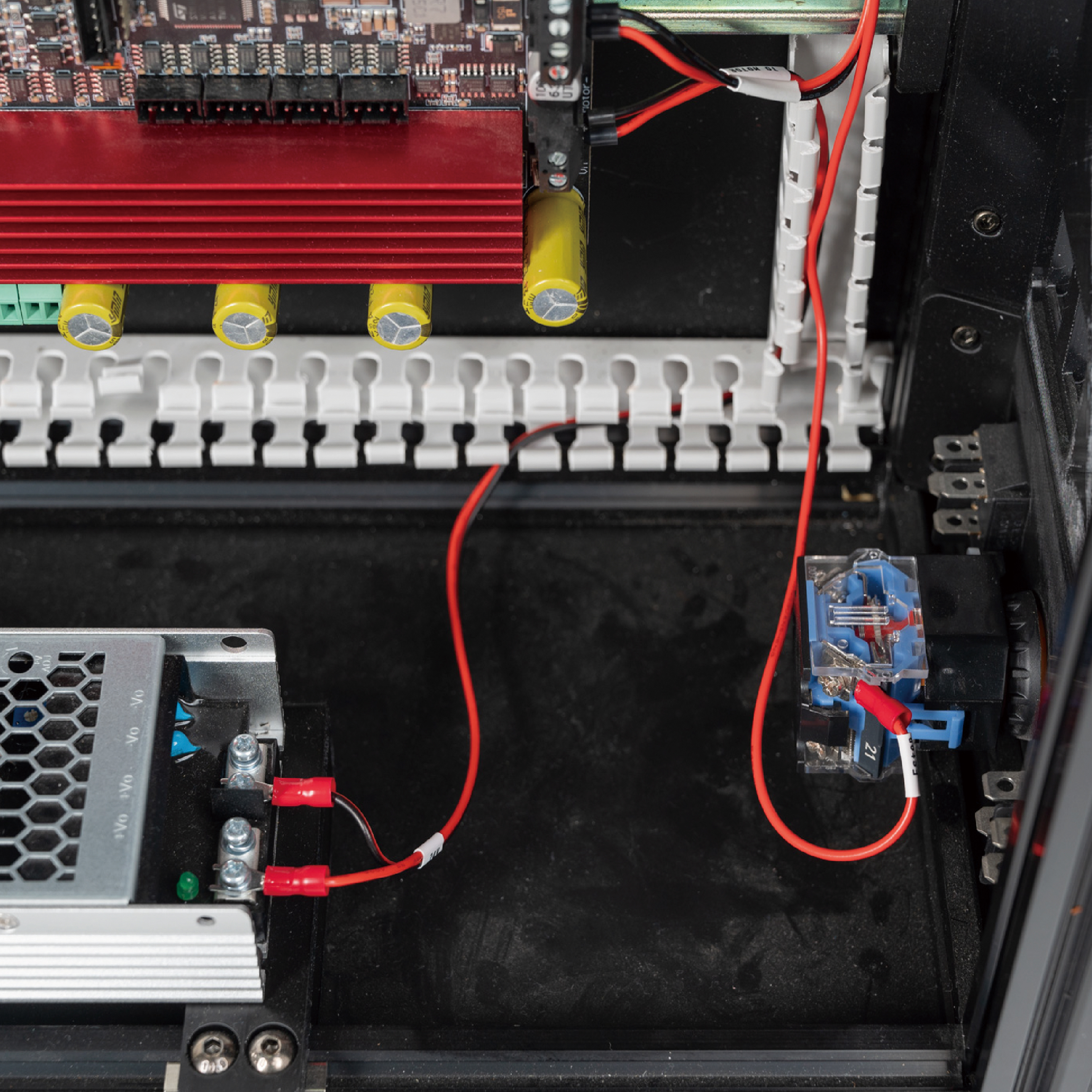
- Use the cable that is labelled TB-3 and ESTOP.
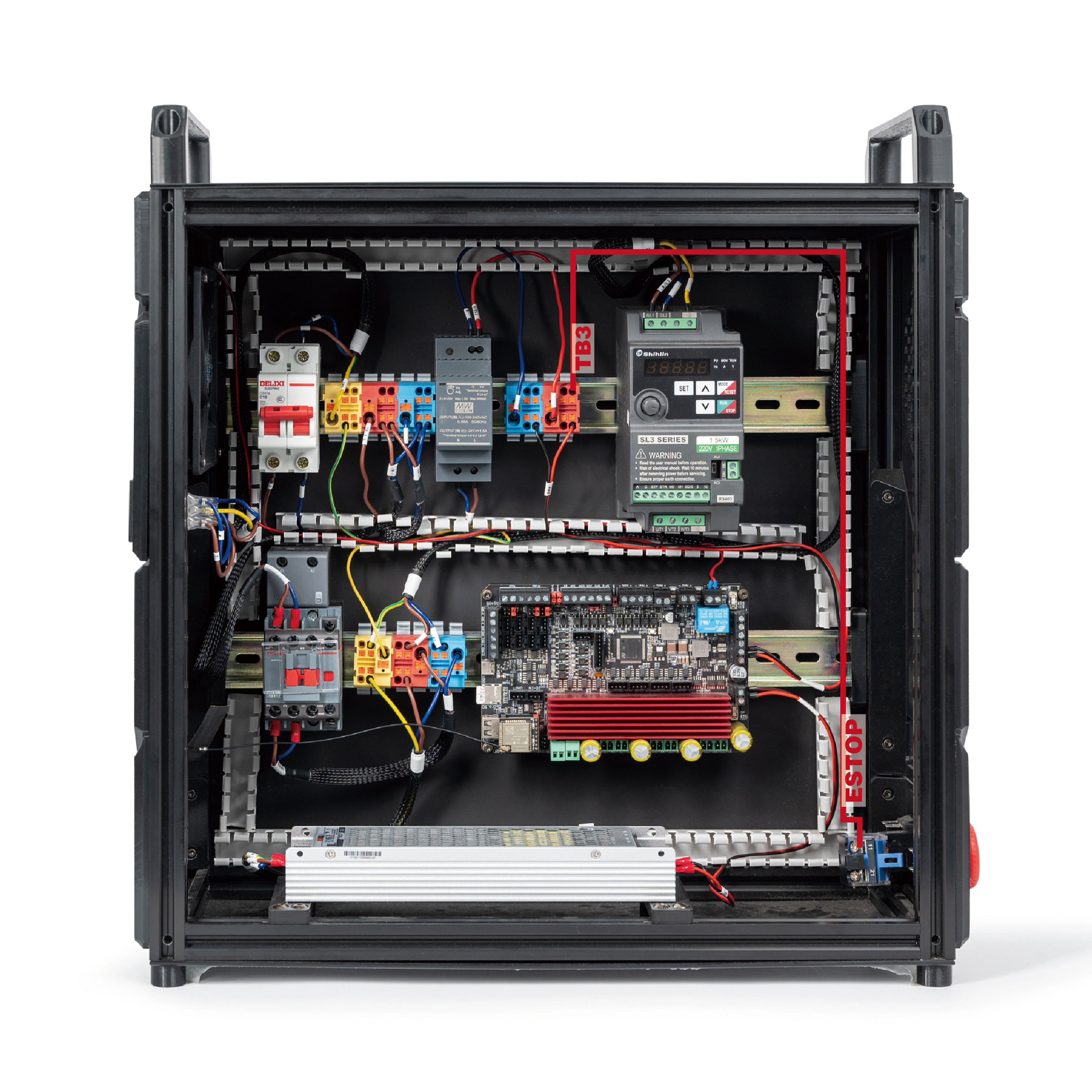
The result:
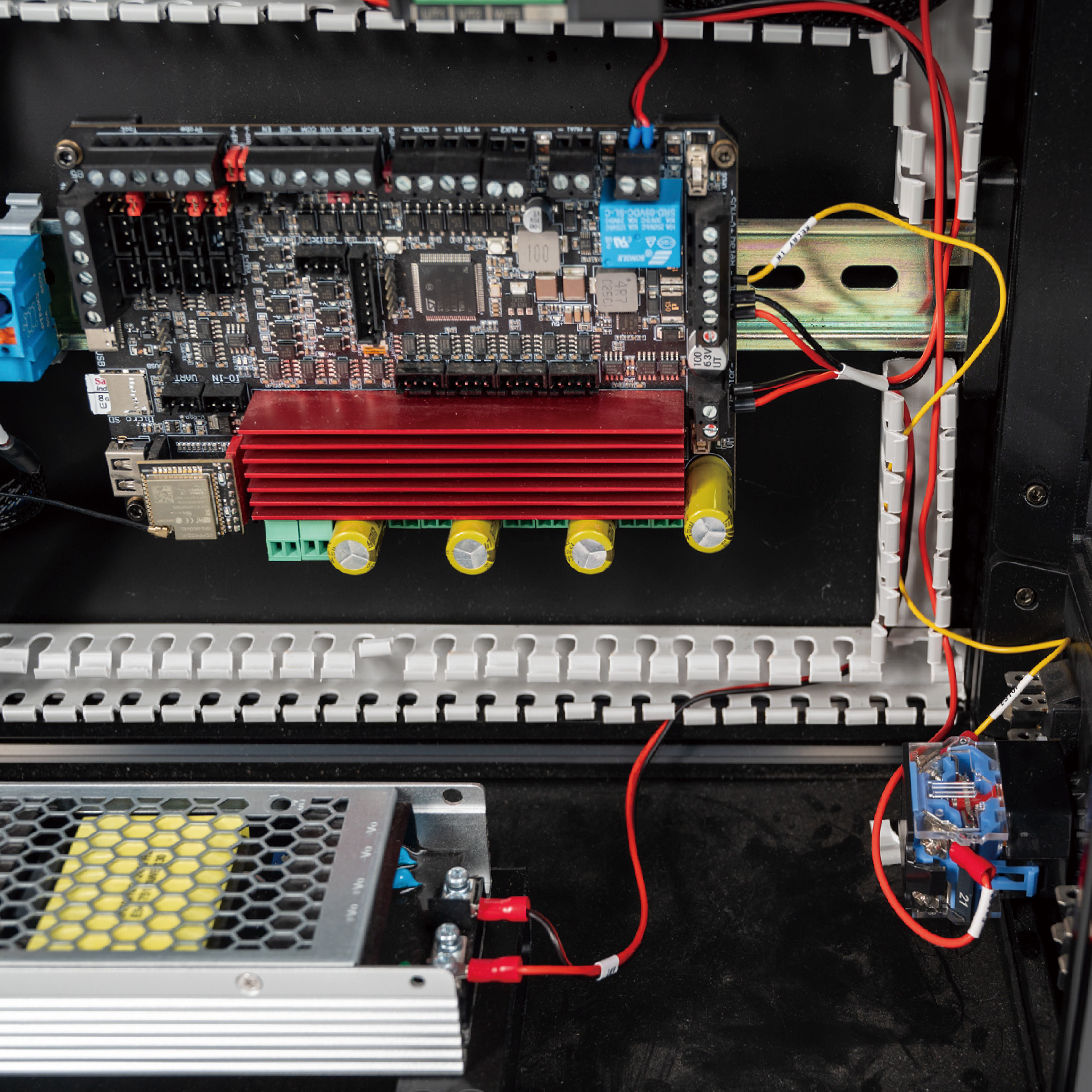
- Use the cable that is labelled ESTOP and RELAY IN.
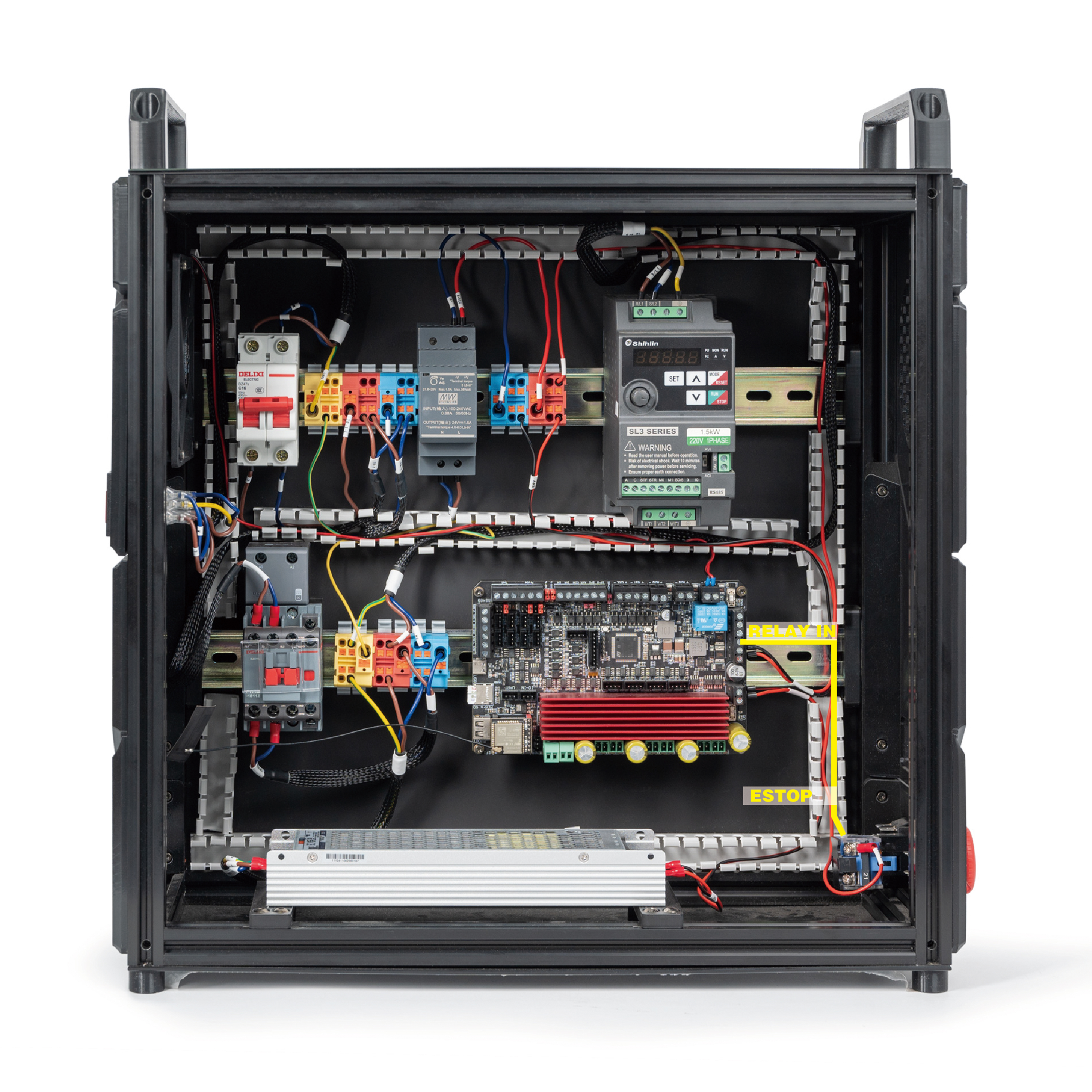
The result:
¶ Connecting the Contactor
- We will connect the contactor and the mainboard. Please follow the following diagram:
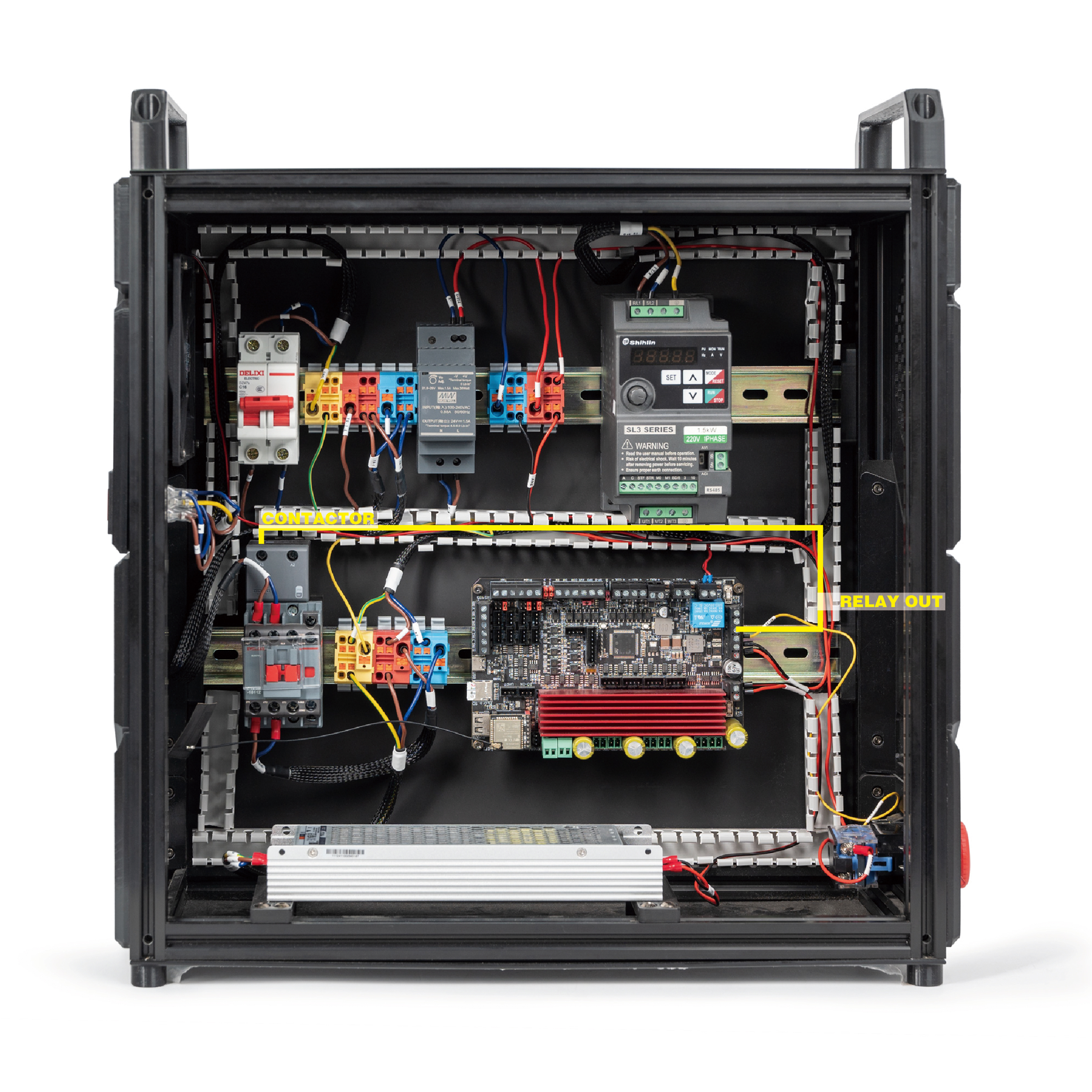
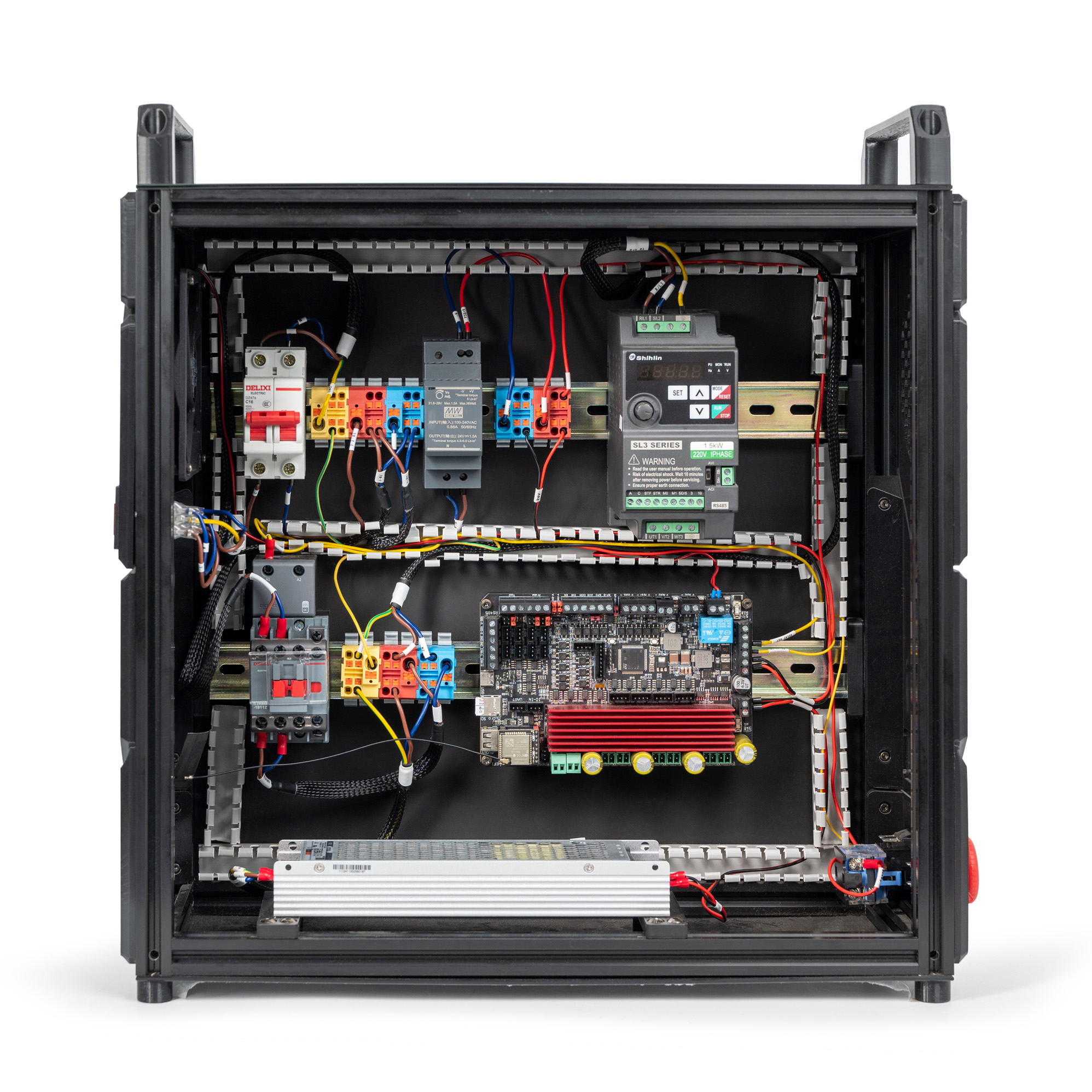
The result:
- Next we will connect the contactor and terminal.
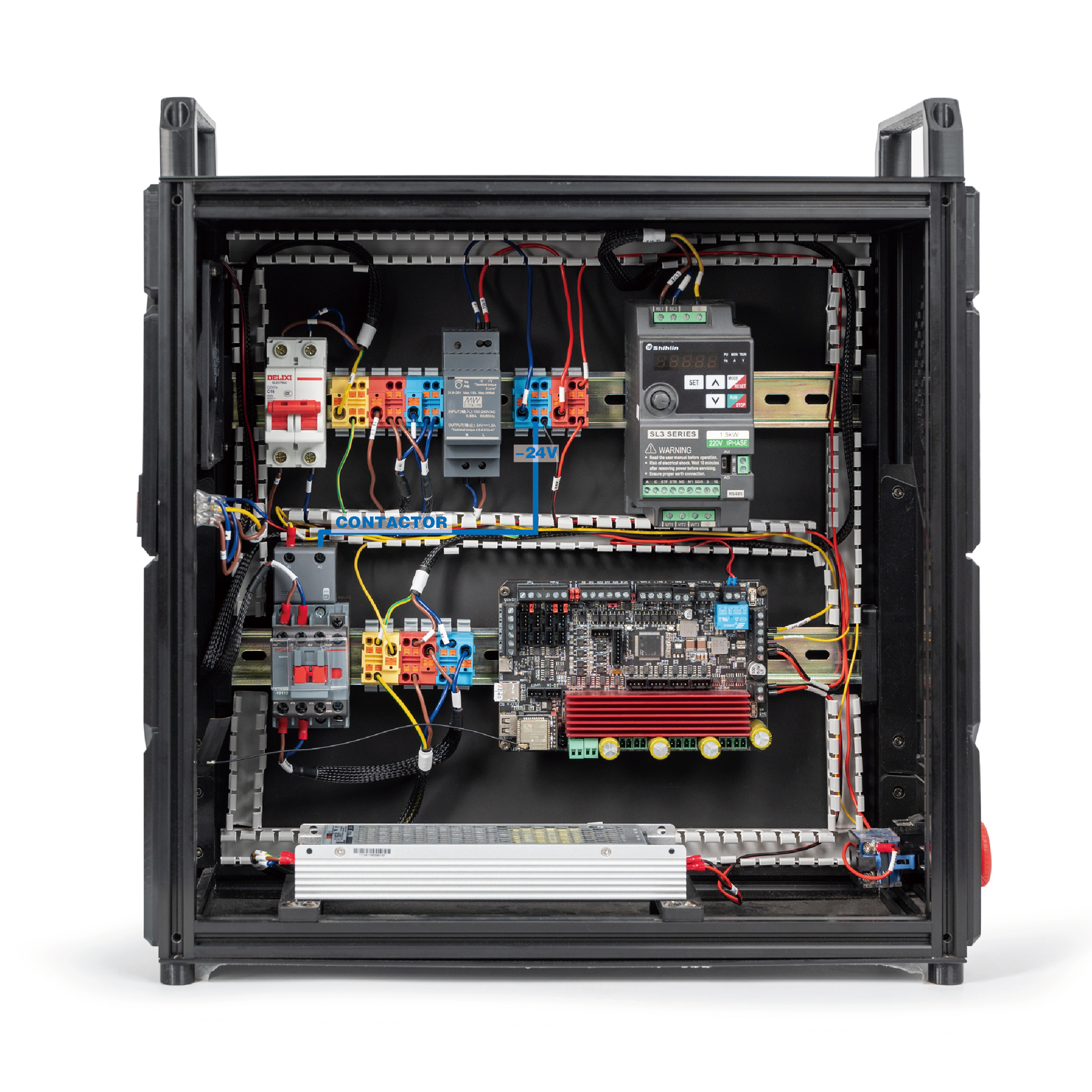
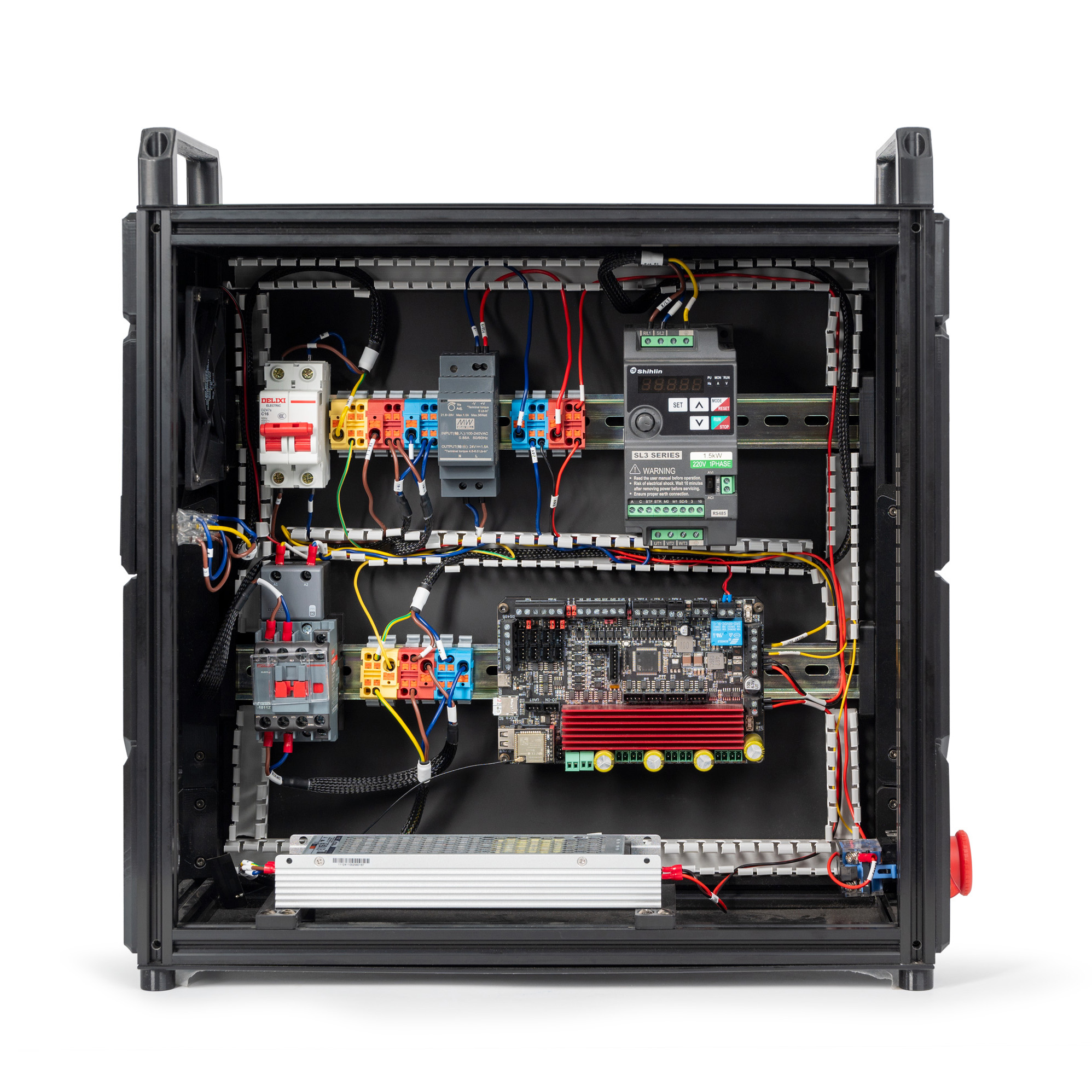
The result:
¶ Connecting the Mainboard and the VFD
In this step, we will connect the mainboard and the VFD. There are 3 ways of wiring and you just need to choose one of them. Follow the following diagram:
- The first one:
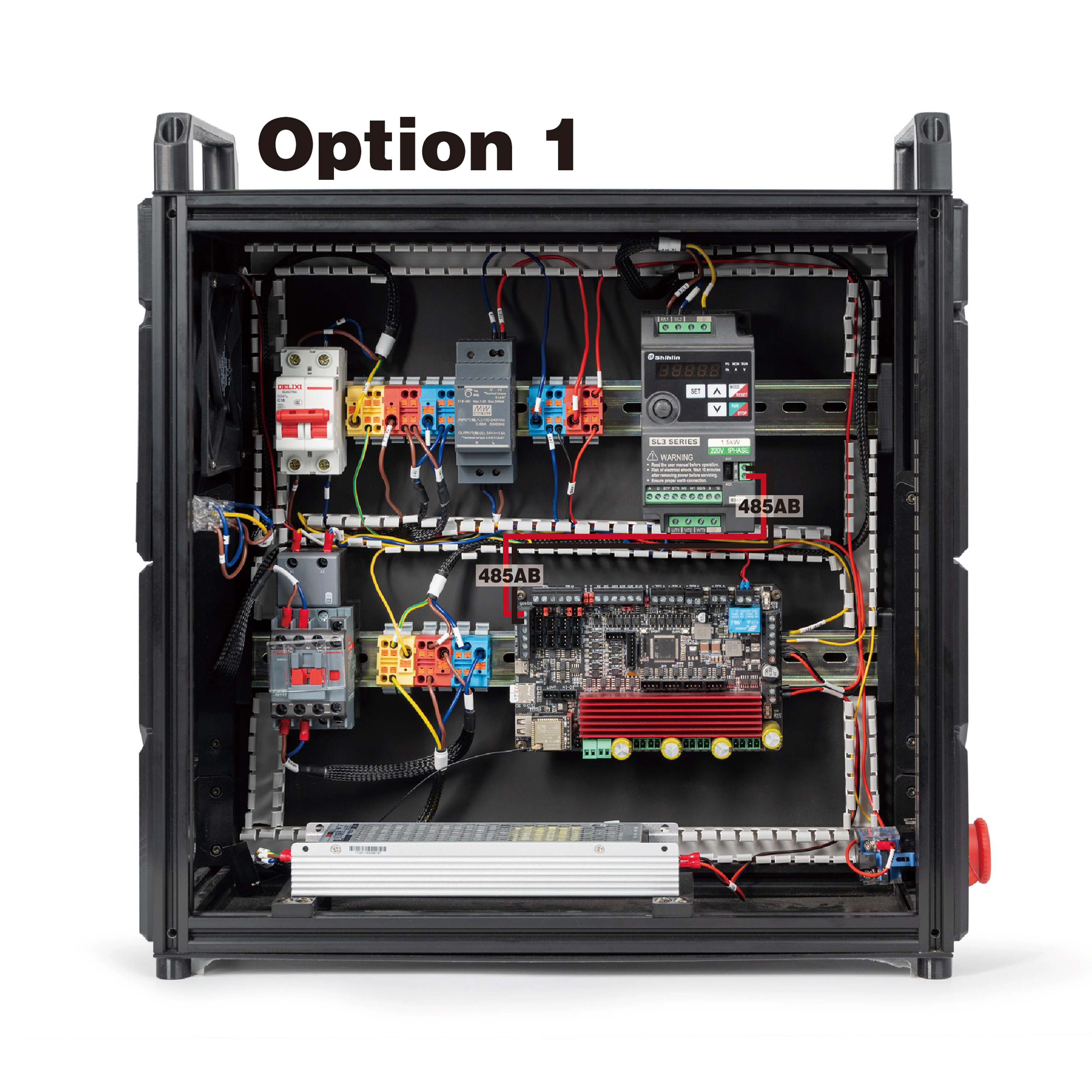
The result:
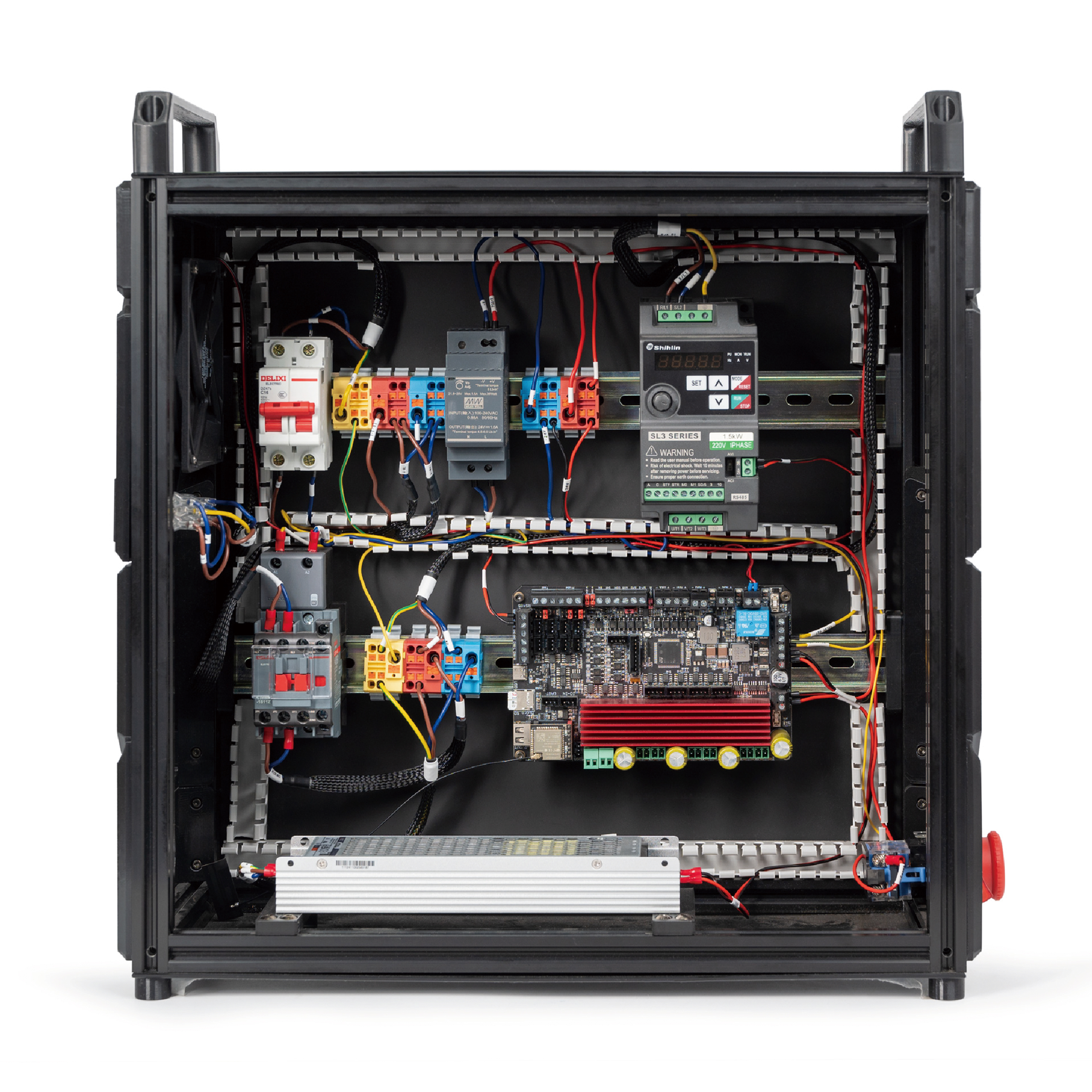
- The second one:
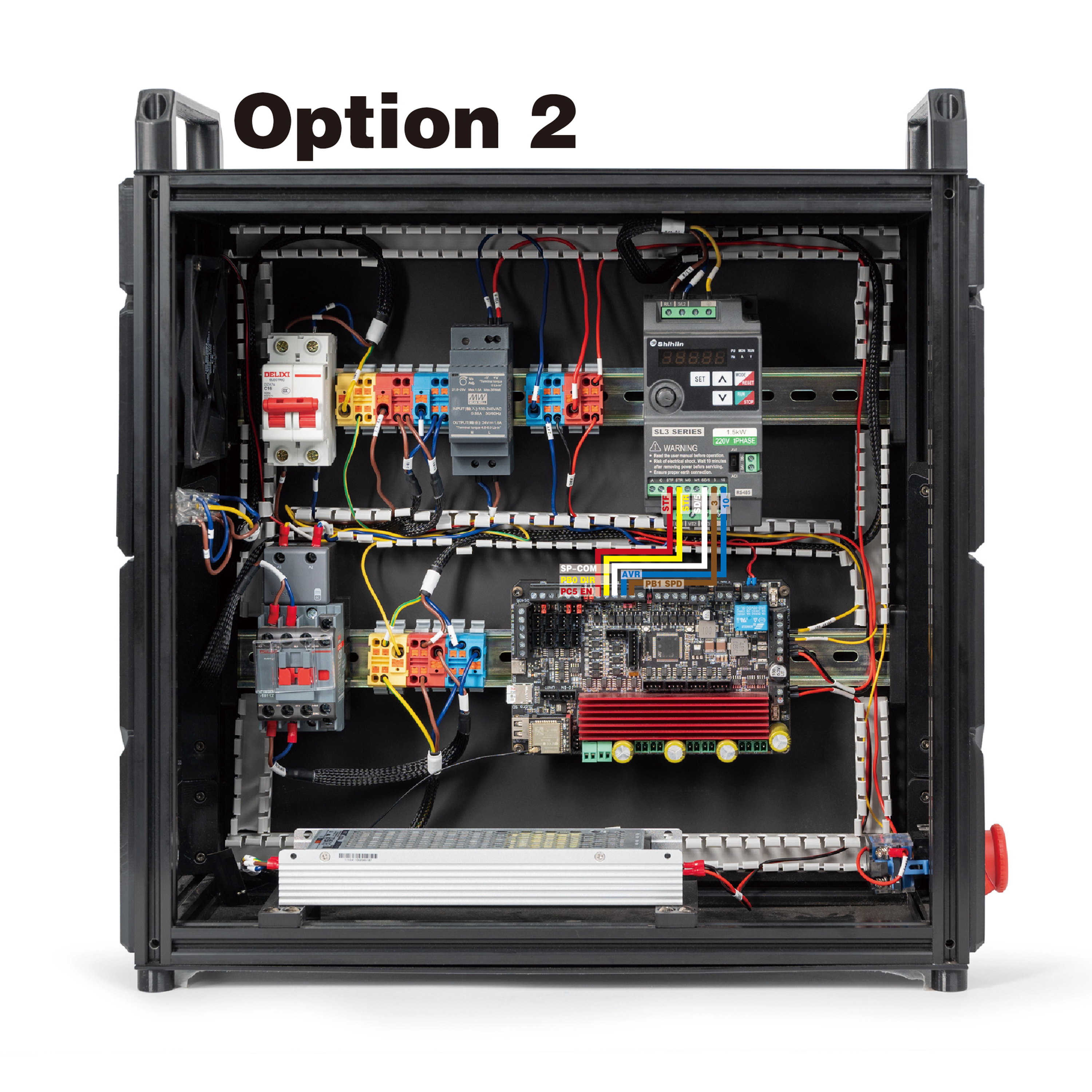
The result:
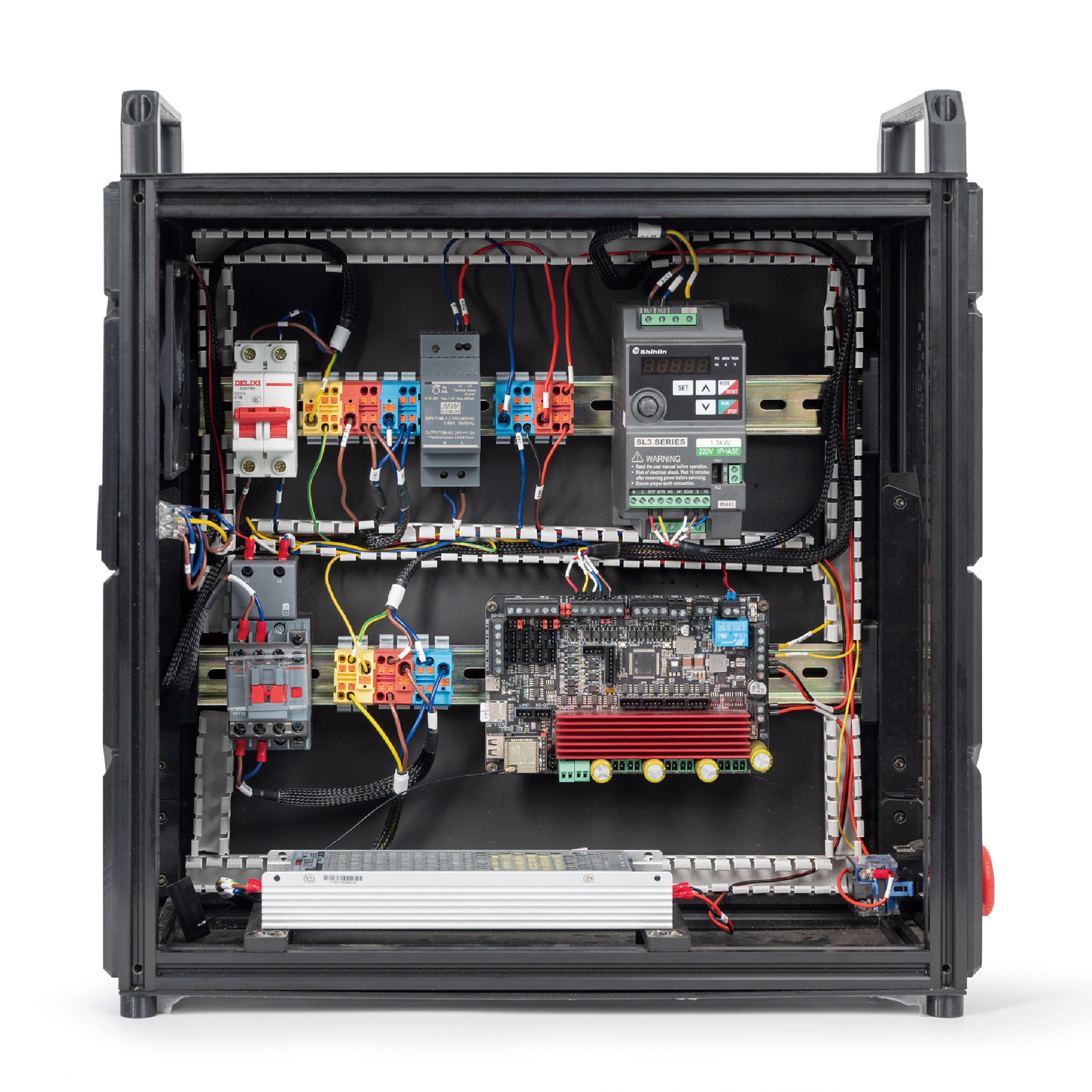
- The third one:
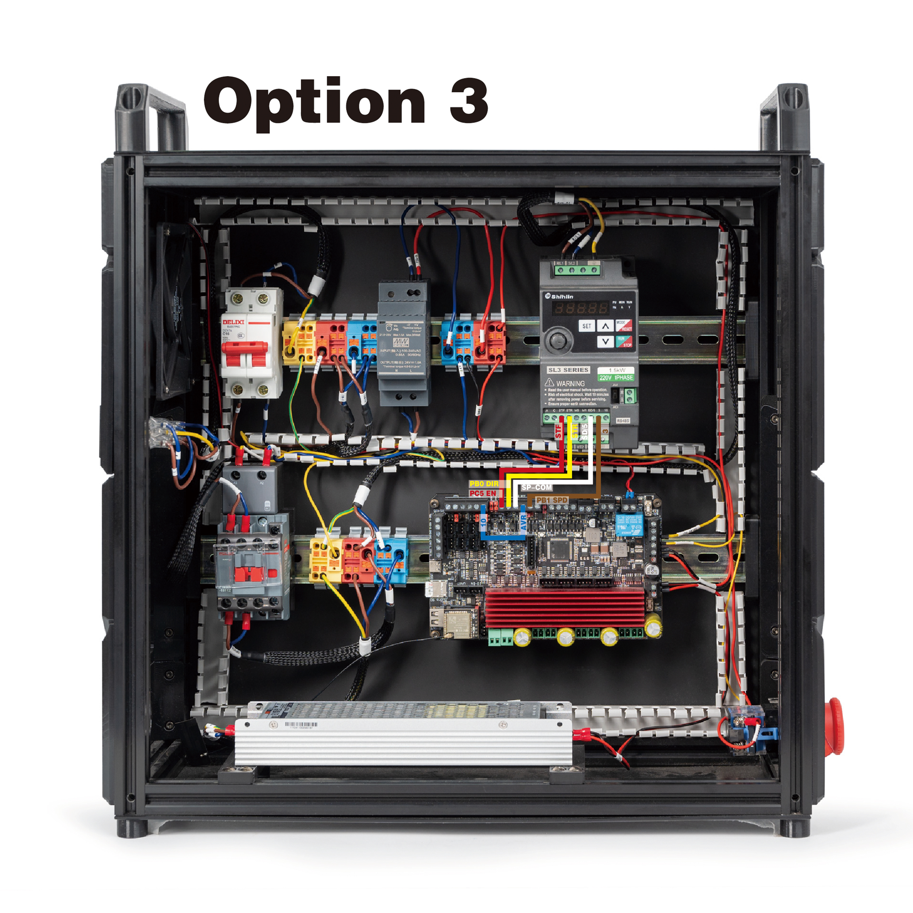
The result:
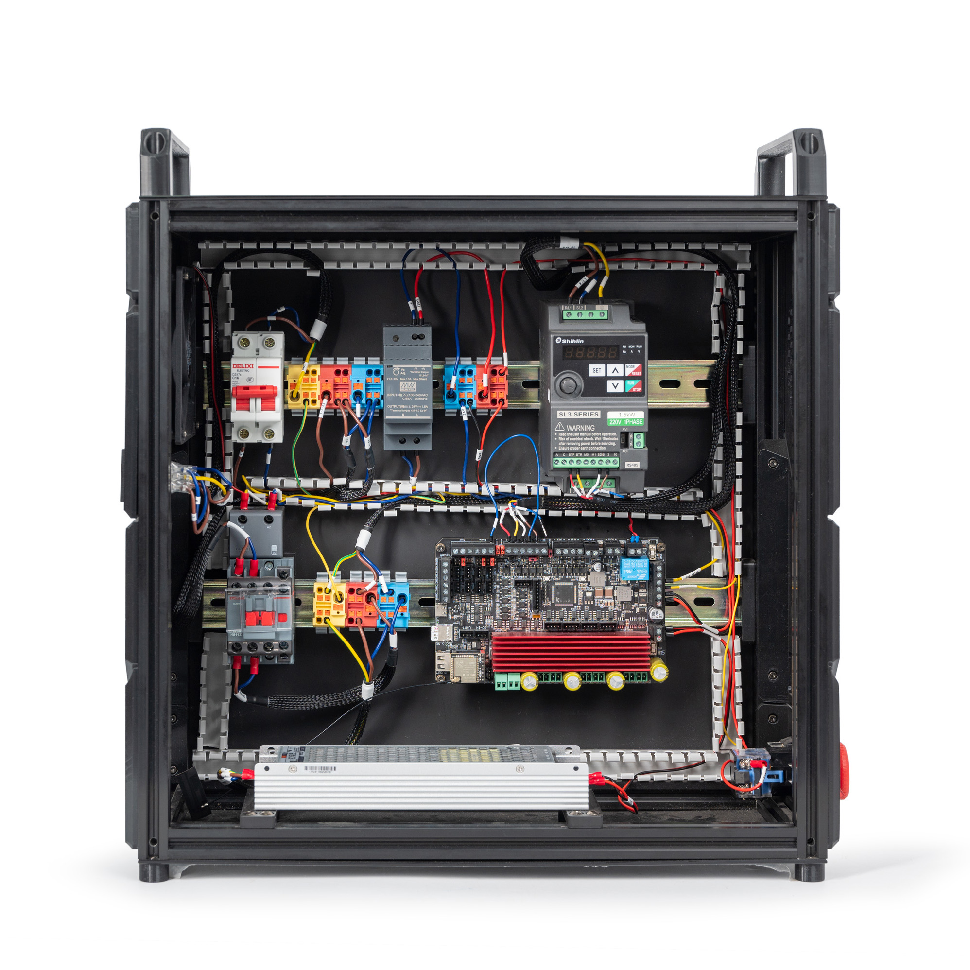
¶ Connecting the Mainboard and the E-stop
In this step, we will connect the mainboard and the E-stop. Please follow the diagram:
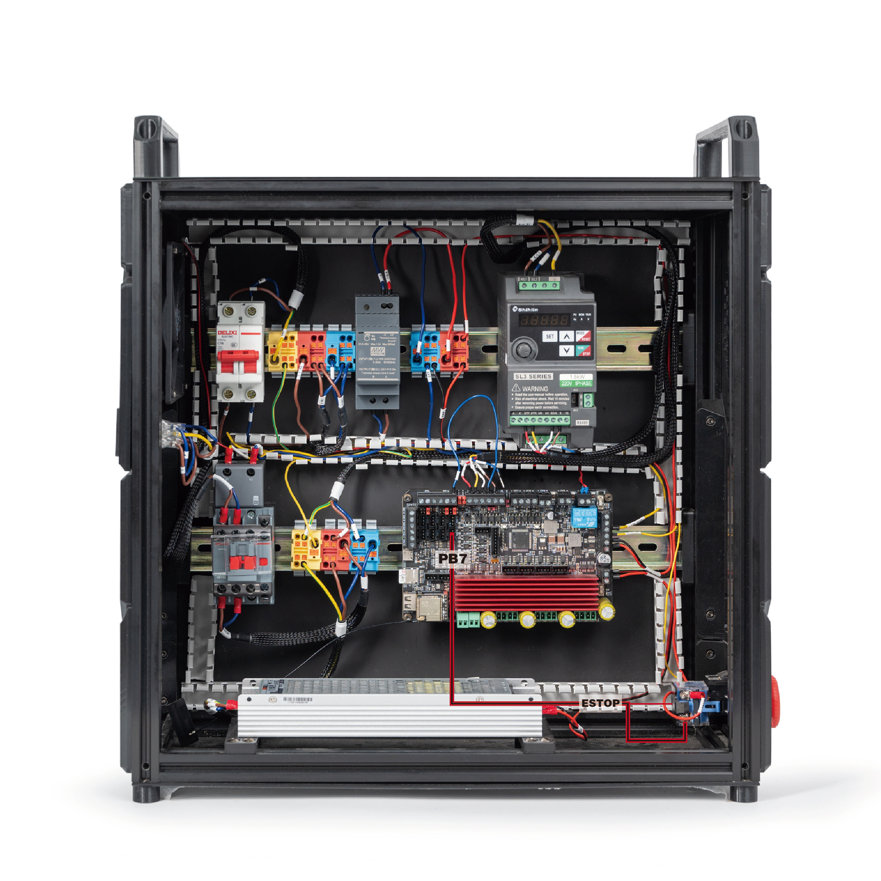
The result:
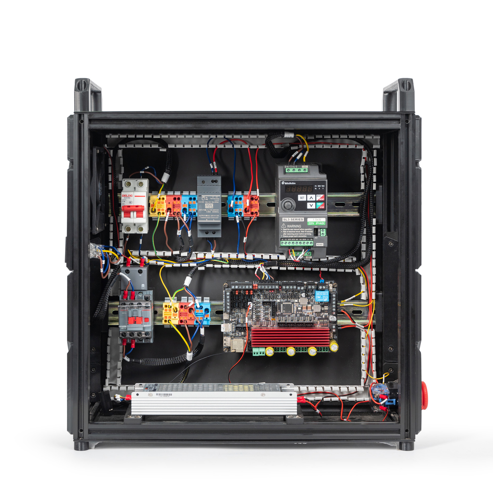
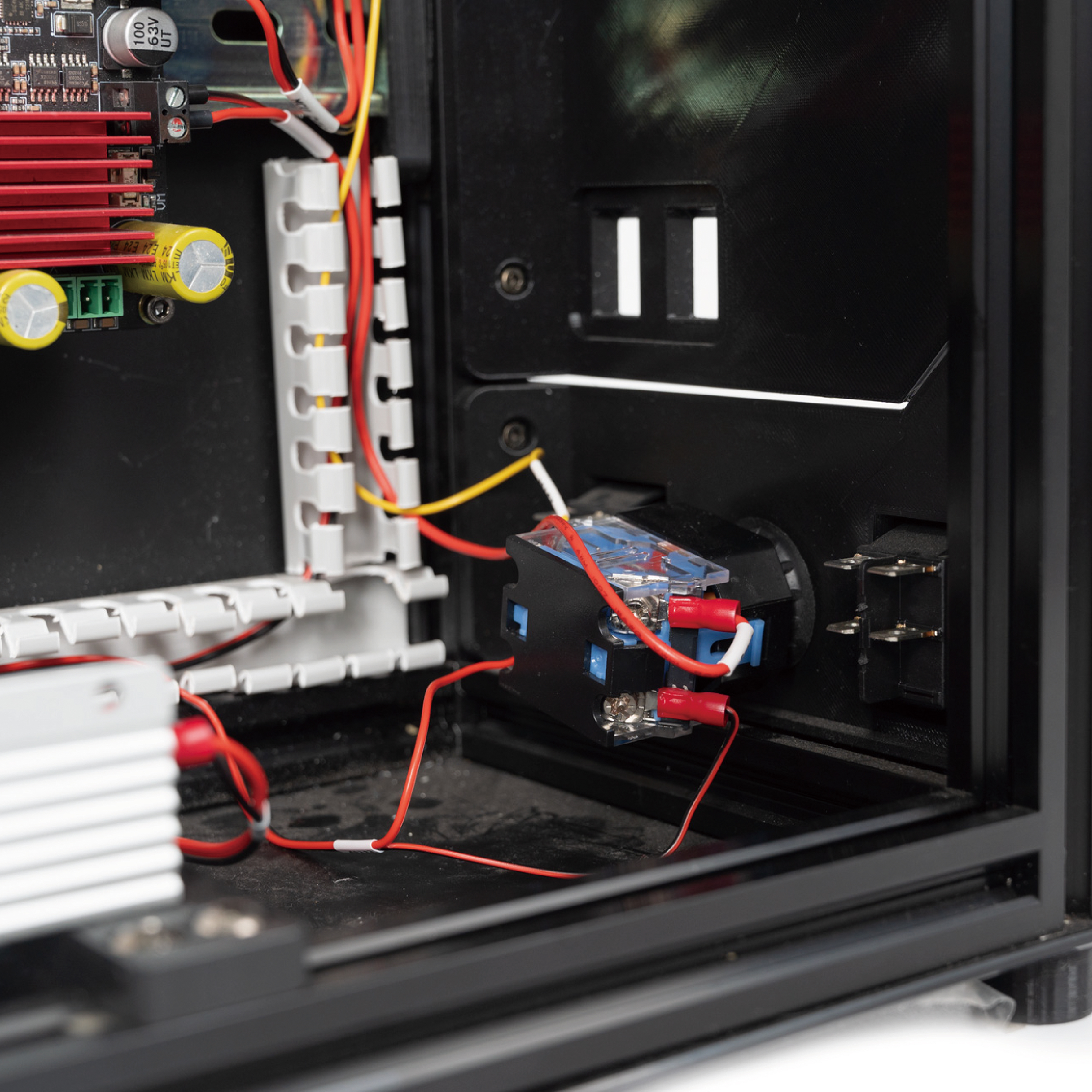
¶ Connecting the Mainboard and the Terminals
In this step, we will connect the mainboard and the terminals. Use the cable labelled VMOS and TB3-24V. Follow the diagram:
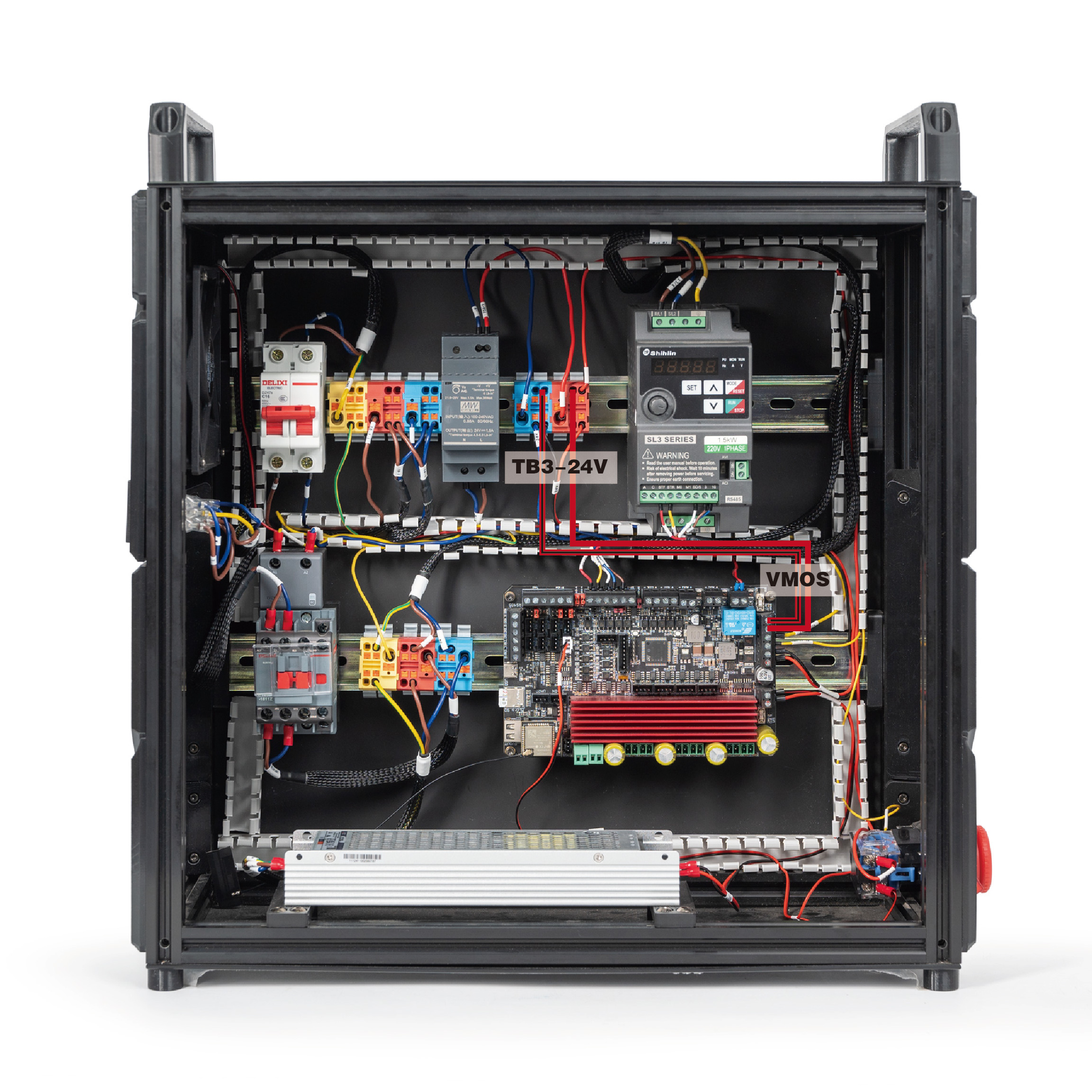
The result should look like this:
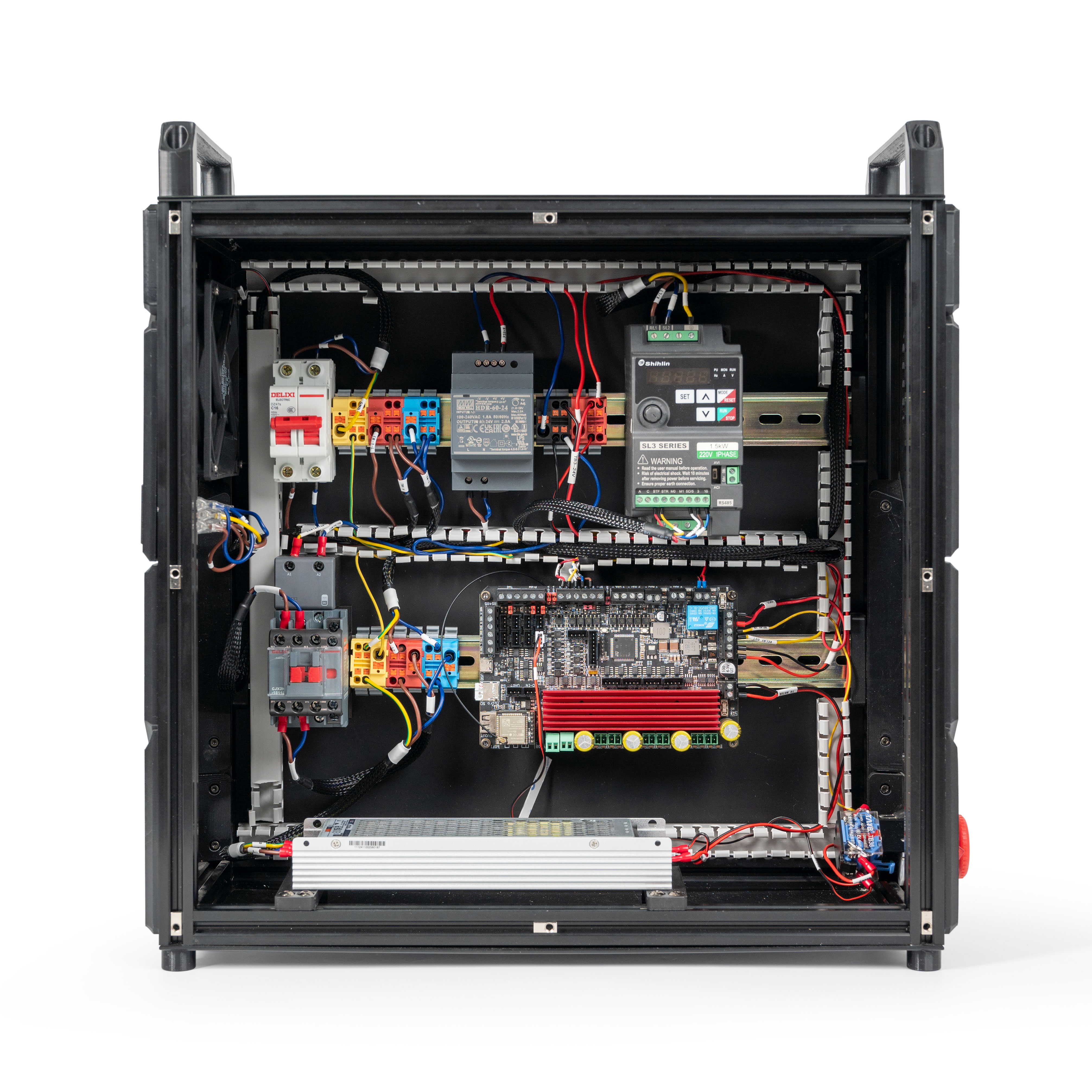
¶ Finish Line
Congratulations! You have completed all the wiring, all that is left now is to cover up the wire ducts!