¶ Printing and Preparing Printed Parts
The printed parts files are found here, print using PETG or ABS filament, with 0.2mm layer height and 40% infill.
The parts shown in this guide are printed with grey filament to provide better visual contrast. However, the provided filament in this kit is black. You can of course use your own filament and colour of choice.
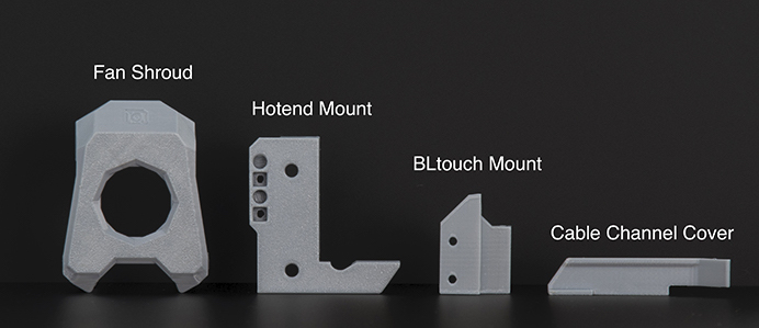
Overhang supports are built into the printed parts files. Remember to remove the supports before assembly! See photos below.

¶ Partially Disassembling Original Ender 3
¶ Ender 3 Toolhead Disassembly
Before we start, remember to complete shutdown your printer and unplug it from its power source!
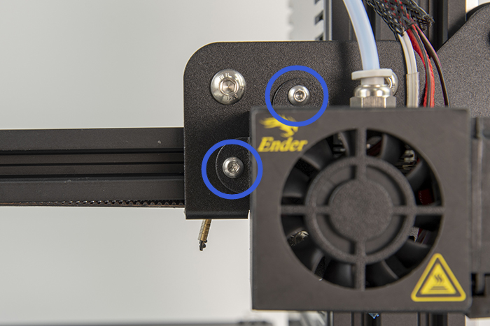
Remove the outer metal housing by unscrewing the two screws here.
Unscrew the hotend from the X carriage.
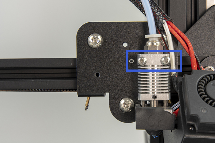
Leave the hotend and metal housing dangling for now. We will deal with the wiring in the next step.
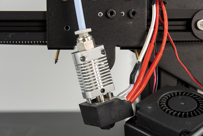
Remember to store all the unused, disassembled parts in a safe place in case you want to restore the printer to its original state.
¶ Modifying the Wiring
In this step, we will remove the original mesh cable sleeve of the toolhead wire harness with an open type cable sleeve that is easier to manipulate. Start by cutting off the nylon zip ties holding the toolhead harness.

Now remove the cover of the motherboard case. Before proceeding further, take a photo of the motherboard while all the cables are still plugged in.
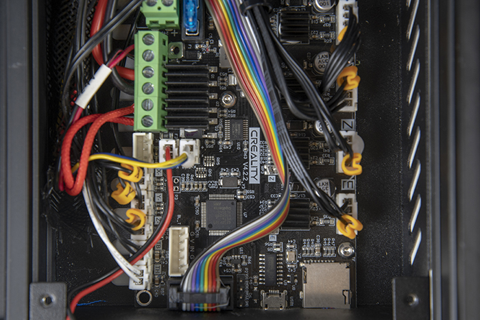
Unplug the thermistor and heater cables from their connectors. Check the photos below.
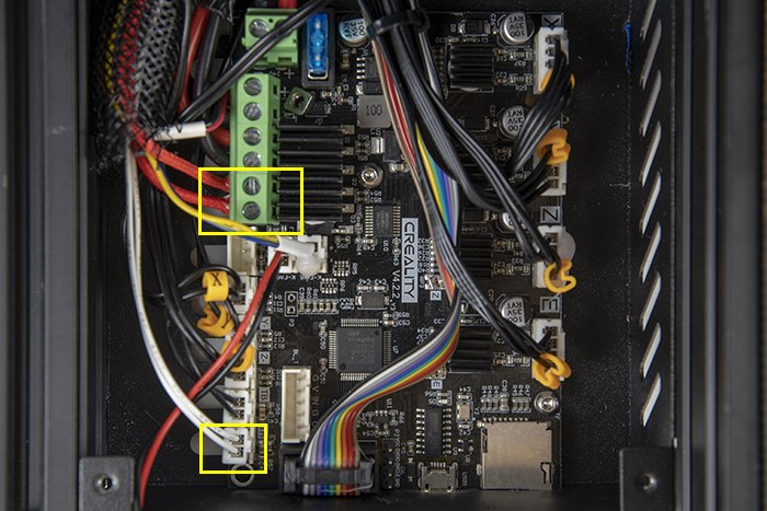
Pull out the thermistor and heater cables from the cable sleeve starting from the toolhead side.
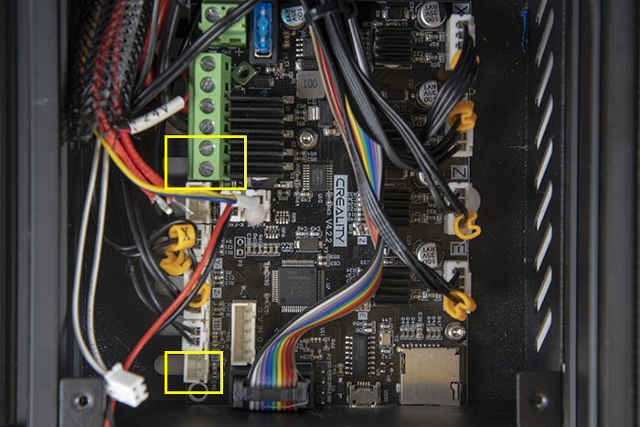
Unplug the two fan cables located in the photo shown below. Pull out the both the fan cables (along with the cable sleeve) from the motherboard case. We will not be using the original fans – you can store these away.
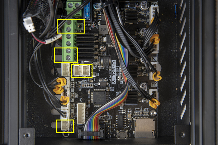
¶ Hotend Mount Assembly
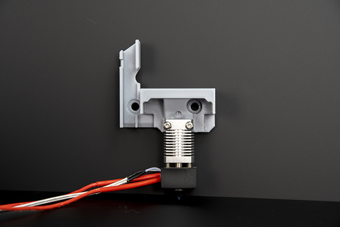
Take the hotend mount and insert two M3 square nuts in the back as shown in the photo. Make sure the square nuts are fully seated into the recess of the printed part.

Flip around the hotend mount and install the hotend with two M3x20 screws. Make sure the screws fully engage the square nuts at the back of the mount and are fully tightened.
Disassemble the two top V wheels from the X carriage. Note the order of the spacers and nylon nut.
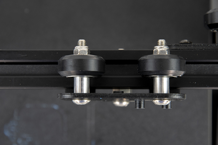
Now we will reassemble the V wheels but with the hotend assembly attached to the X carriage.
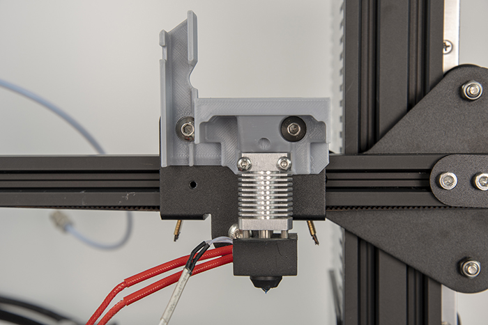
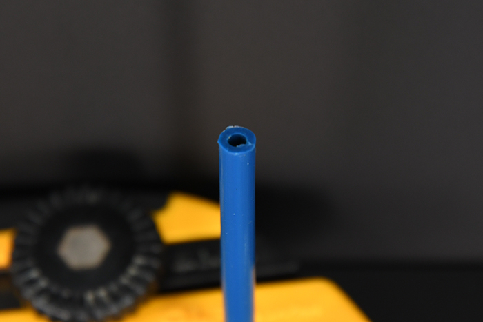
Finally, install the Capricorn Teflon tube and insert it into the hotend and shown. Make sure it is seated all the way to the bottom of the hotend.
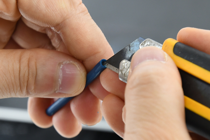
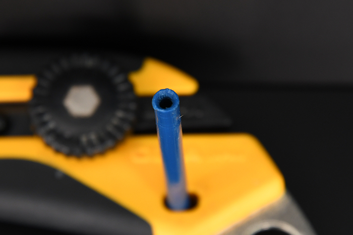
When installing the orbiter, you might find that the Teflon tube is too long. If that is the case, you will need to trim it short. Finally, make sure to cut a countersink into the end of the tube.

¶ Fan Assembly
¶ Part Fans
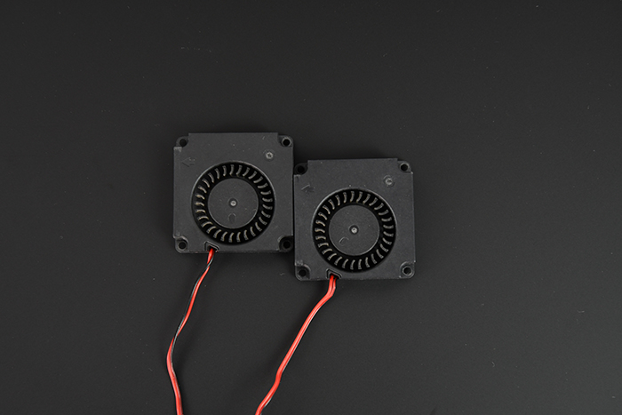
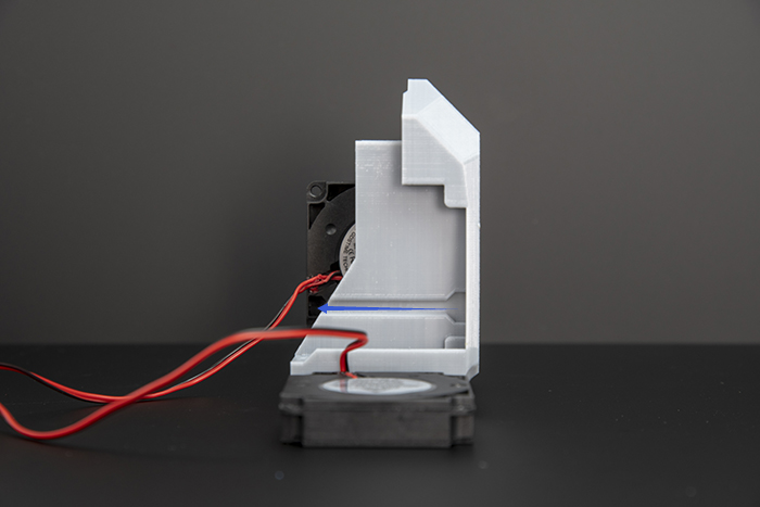
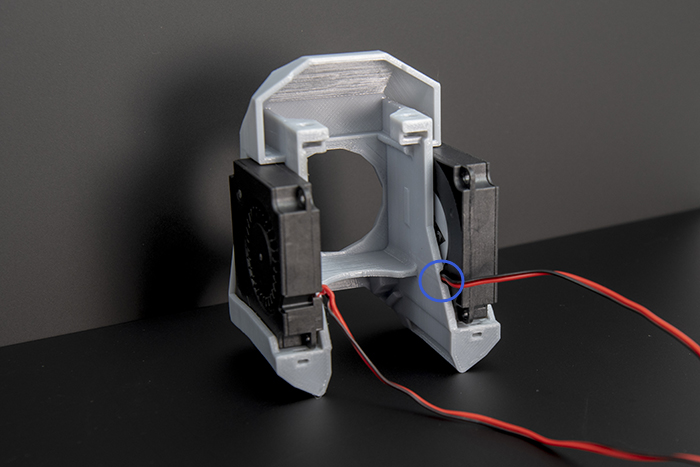
Take the two blower fans and press fit them into the fan shroud while paying close attention to the orientation – The fan openings should face outwards and the exhaust should face downwards.
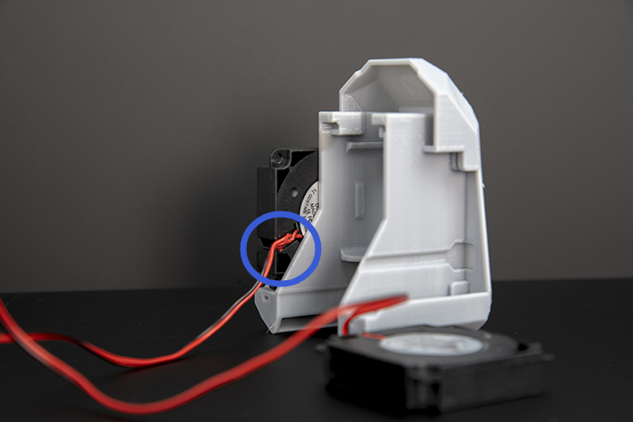
Also note the wire channel in the printed part. The left blower fan will have its cable facing the inside of the fan mount, this fan’s cable will need to be routed long the wire channel.
¶ Hotend Fan
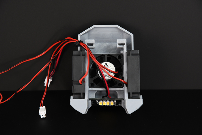
Press fit the hotend fan into the mount as shown in the photo. Pay close attention to the orientation of the fan cables.

¶ Hotend Lights
Take the LED PCB and press it into the fan mount as shown in the photo. Make sure to press it in all the way – you should hear a snap when this happens.
¶ Installation onto the Carriage
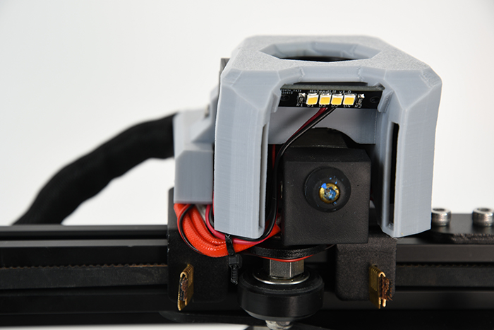
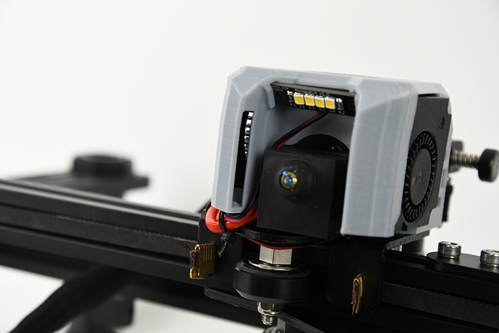
Put two M3 square nuts into the slots shown in the photo. Now install the fan assembly onto the X carriage using two M3x10 flathead screws. Refer to the photo below.
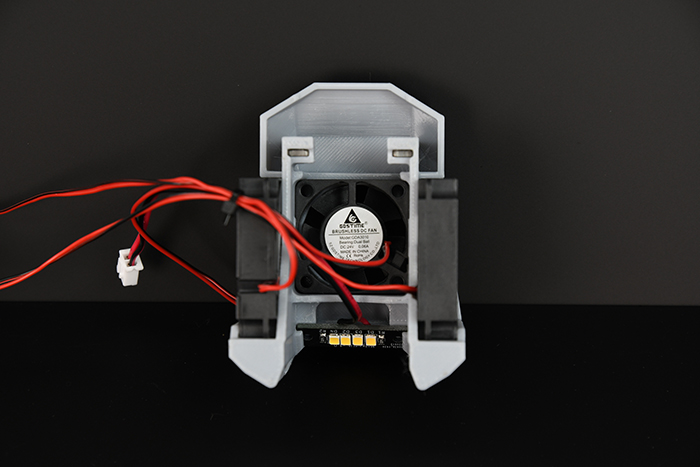
Take your time while installing the fan assembly, pay close attention to cable management. Eventually, all the cables will need to be routed via the cable channel on the left. Refer to the photos below.

¶ Installing Orbiter
Install three M3 square nuts into the top of the hotend mount as shown in the photo.
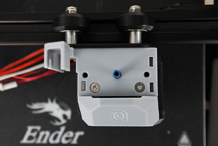
Use two M3x12 screws to install the Orbiter extruder onto the hotend mount.

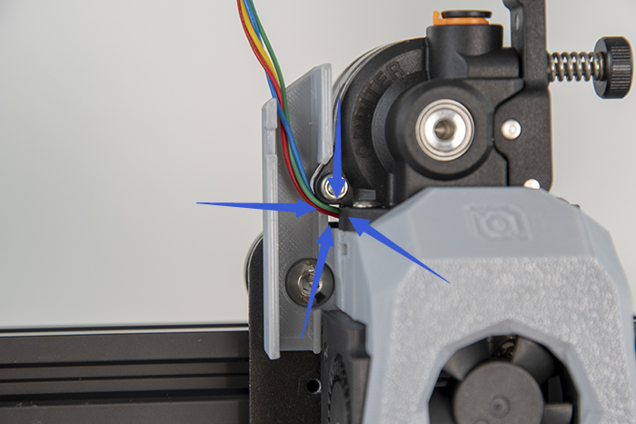
Take the hotend fan extension cable and connect it to the short hotend fan and LED PCB cables respectively.
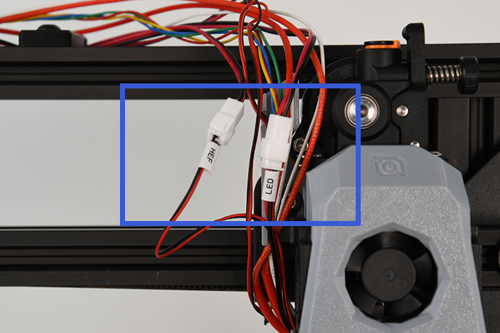
Place all the cables into the cable channel and cover them up with the cable cover. Use an M3x10 screw to fasten the cover.
¶ Optional BLtouch Mount
If you have a BLtouch or CRtouch, the mount can be installed on the left side of the toolhead. First insert an M3 square nut into either side of the mount.

Install the part onto the toolhead using two M3x10 screws.
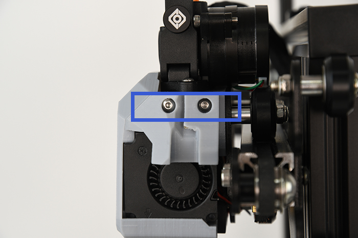
¶ Electronics Hookup
Use the provided cable sleeve to wrap up all the cables (orbiter motor, hotend heater & thermistor, hotend fan, part fan)

Insert the bundle of cables, back into the motherboard compartment.

Connect the part fans (cable end labelled with PCF).
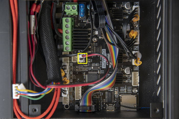
Connect the hotend fan + LED (cable end labelled with HEF + LED). PAY CLOSE ATTENTION TO POLARITY: check with the photo carefully.

Reconnect the hotend heater. Polarity does not matter here.
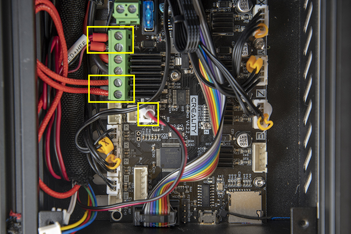
Reconnect the thermistor.
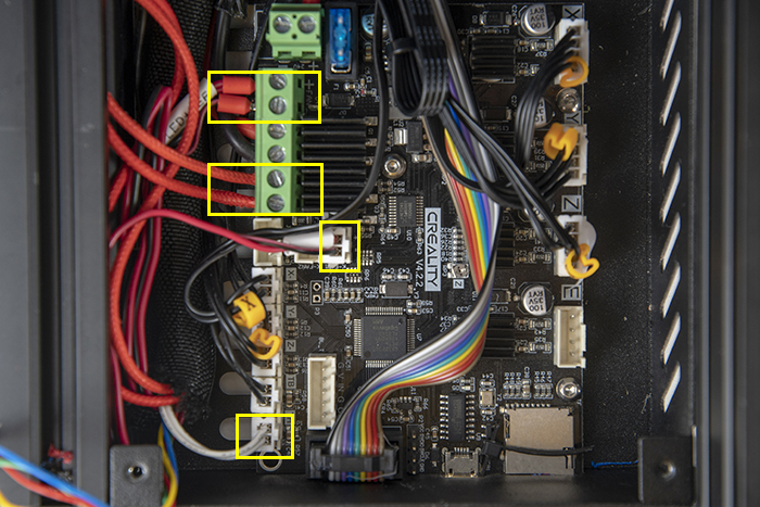
Unplug the original extruder motor and connect the orbiter motor.
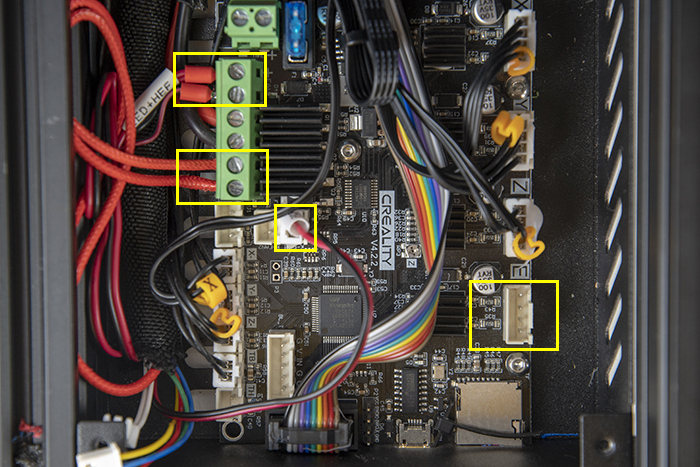
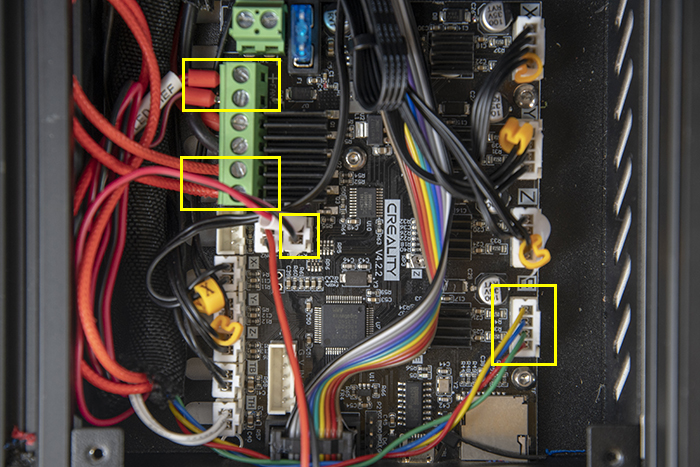
If you unplugged the motherboard fan, plug it back in now.

Finally, cover the motherboard compartment back in!
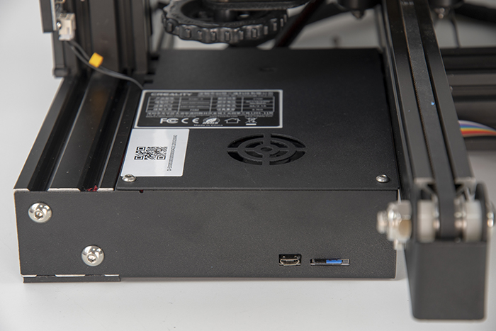
** Setup: please refer Orbiterprojects site.
https://orbiterprojects.com/apogee-ender-3-v2/