This guide contains directions for wiring a Voron V0.1 using the pre-cut, pre-terminated cables included in the LDO kit. Currently, these directions are only compatible with a direct-feed toolhead setup (sorry bowden folks!). Important! Mains wiring should only be performed by certified personnel trained in local regulations and safety standards. If during any step of this guide, you find the images to be unclear, you can always view the high resolution source files here.
¶ Pre-Wired Items
The following items have been soldered to cables for your convenience. In theory, there is no need to solder or crimp anything, unless you wish to add connectors in the middle:
- X, Y, Z endstops
- Print Fan
- Hotend Fan
The following items should have pre-cut lengths, labels, and crimped connectors:
- Hotend Cartridge
- Hotend Thermistor
- Heatbed (with thermal fuse wired in series)
- Heatbed Thermistor (connector housing not installed so the cables can be run through drag chain)
The following cables are labelled and crimped with connectors:
- AC to 24V PSU
- 24V PSU to 5V PSU
- 24V PSU to SKR
- 5V PSU to Raspberry Pi
- USB Micro Power Cable (Rev. A/B/C)
- GPIO Power Cable (Rev. D)
Currently, stepper motor cables are not pre-cut to length (The extruder motor cable should be just long enough). They are purposely left longer than needed for people with different setups. You may choose to cut them or leave them as is during wiring.
¶ Wiring The Power Supplies
¶ Preparing The AC Inlet
Your kit should include a pre-wired AC inlet. Double check that the wiring correct, the final layout should be as follows:
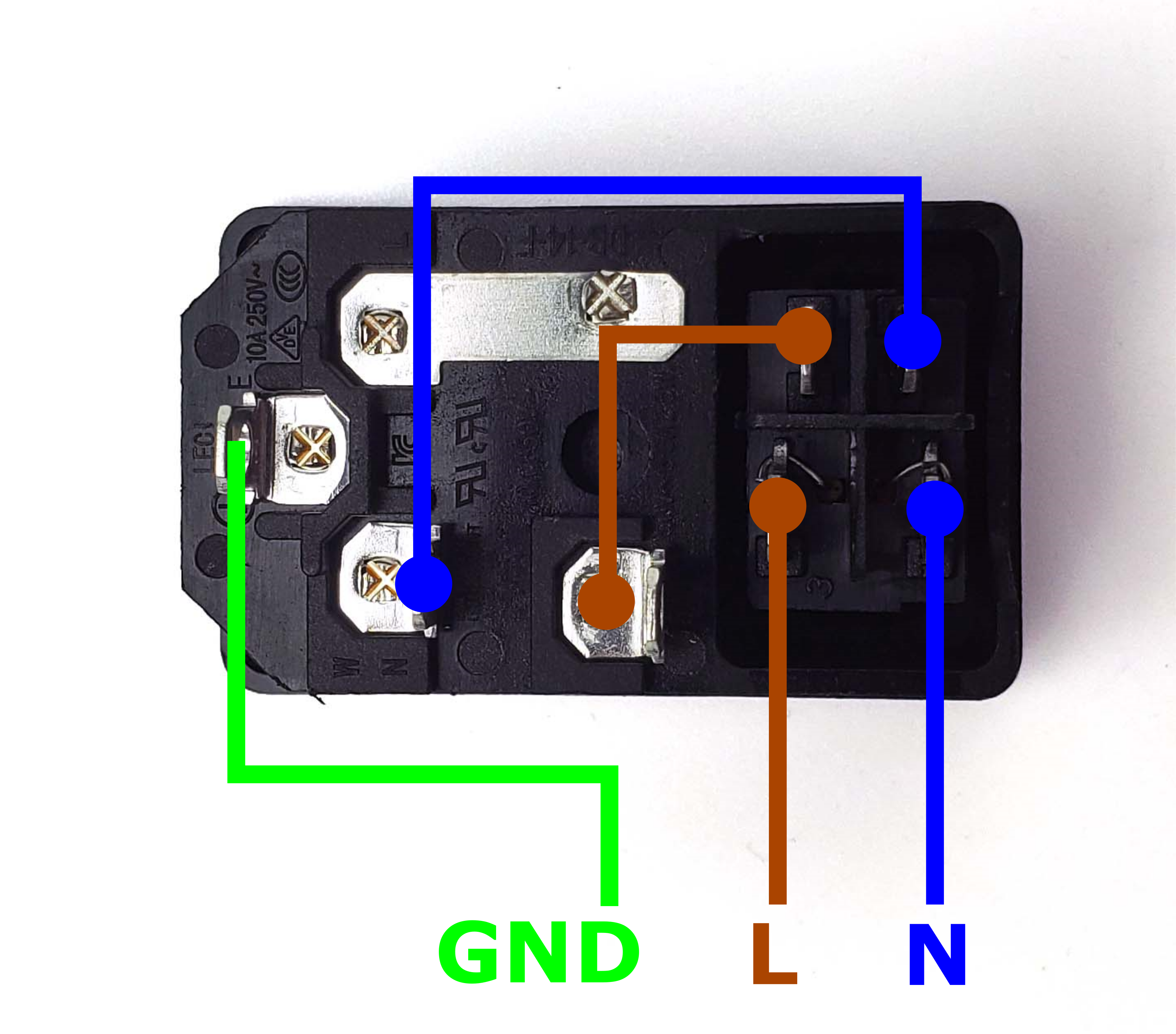
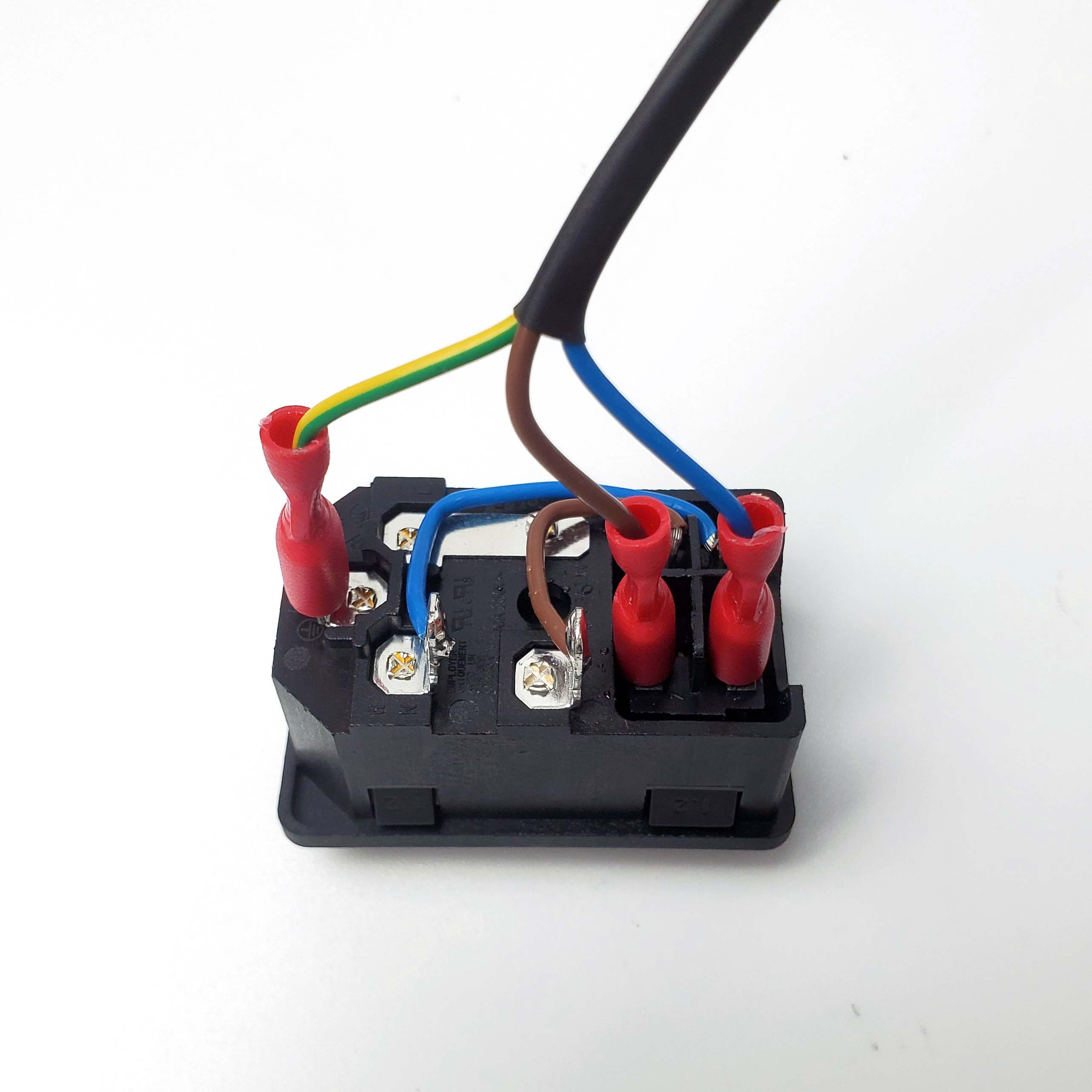
Take the inlet cable included in the kit and attach the wires using the above layout as reference. When wired correctly, your live wire will be protected by a fuse, and the switch on the front side of the inlet will operate correctly (lights up when turned on).
¶ Preparing the Power Supply
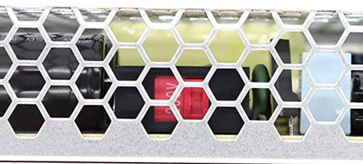
The 24V power supply unit that comes with the kit contains a switch on the side to select between 115V or 230V. Flick the switch to the correct value before powering it on! Failing to do so can destroy the power supply!
¶ Placing The Power Supplies
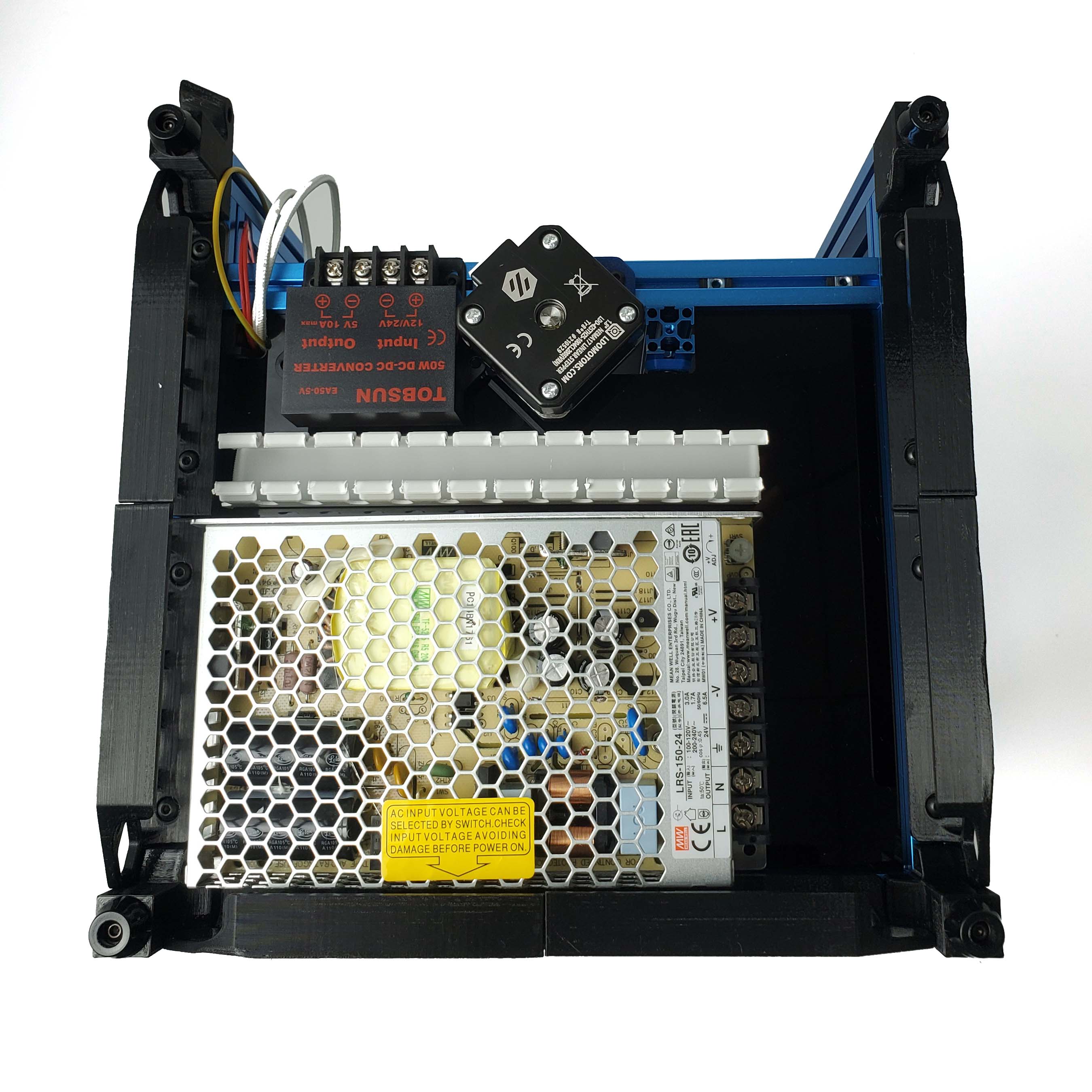
Follow the official manual for how to place the 24V and 5V power supplies. Cut an approximately 16cm long section of PVC wiring duct and place it like this:
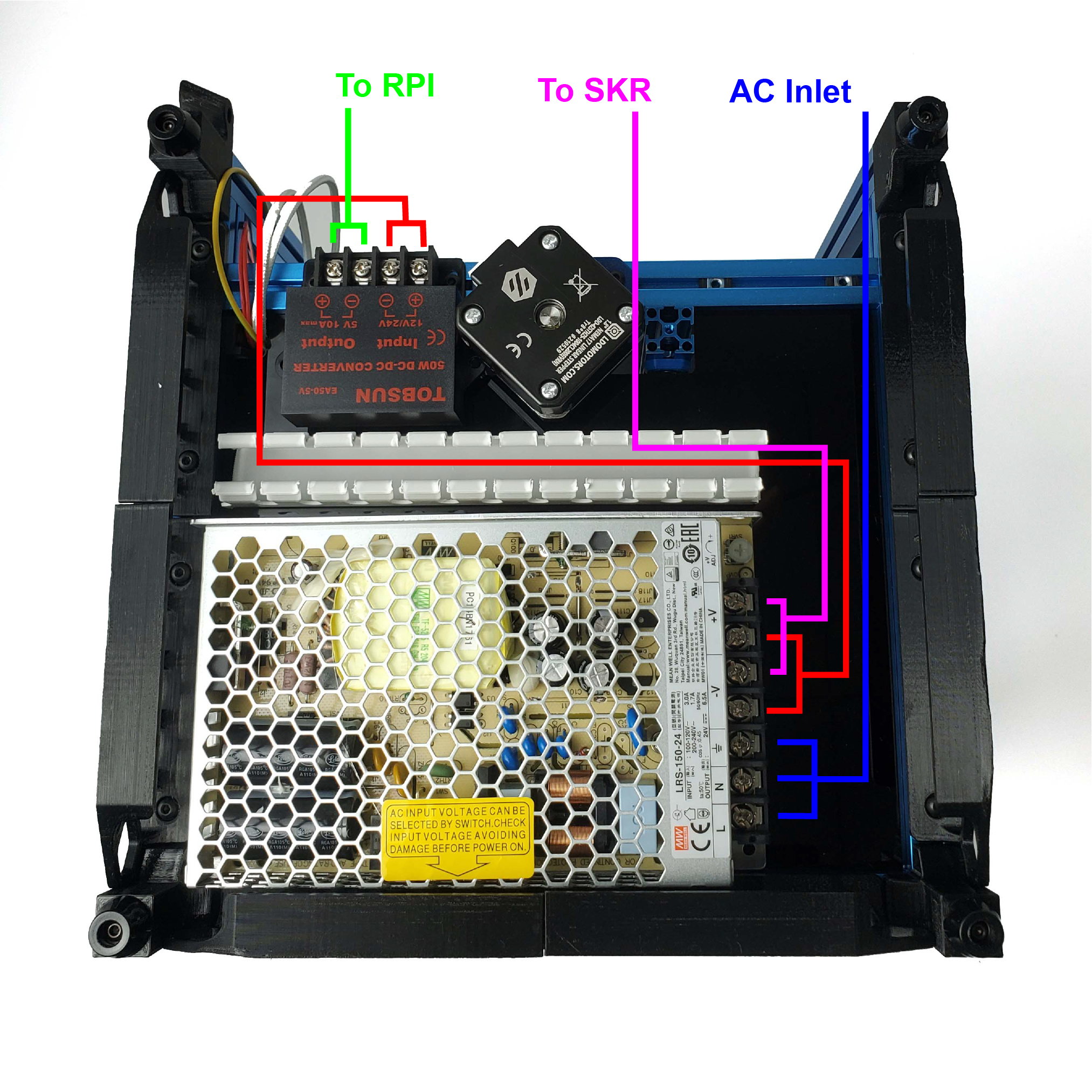
Let's go over how the power supplies will be wired:
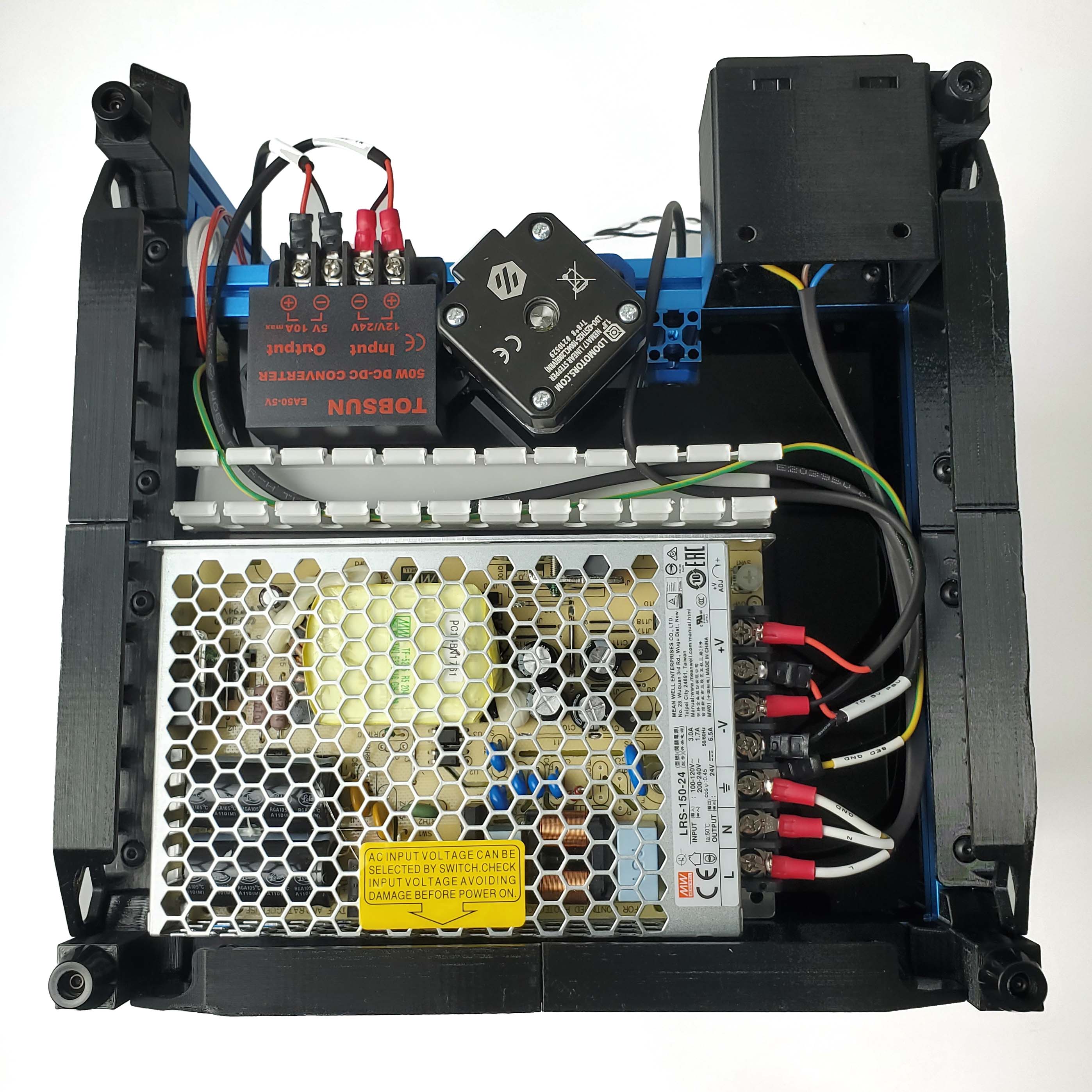
Install the AC inlet and complete the wiring of the power supplies, the end result should look something similar to this:
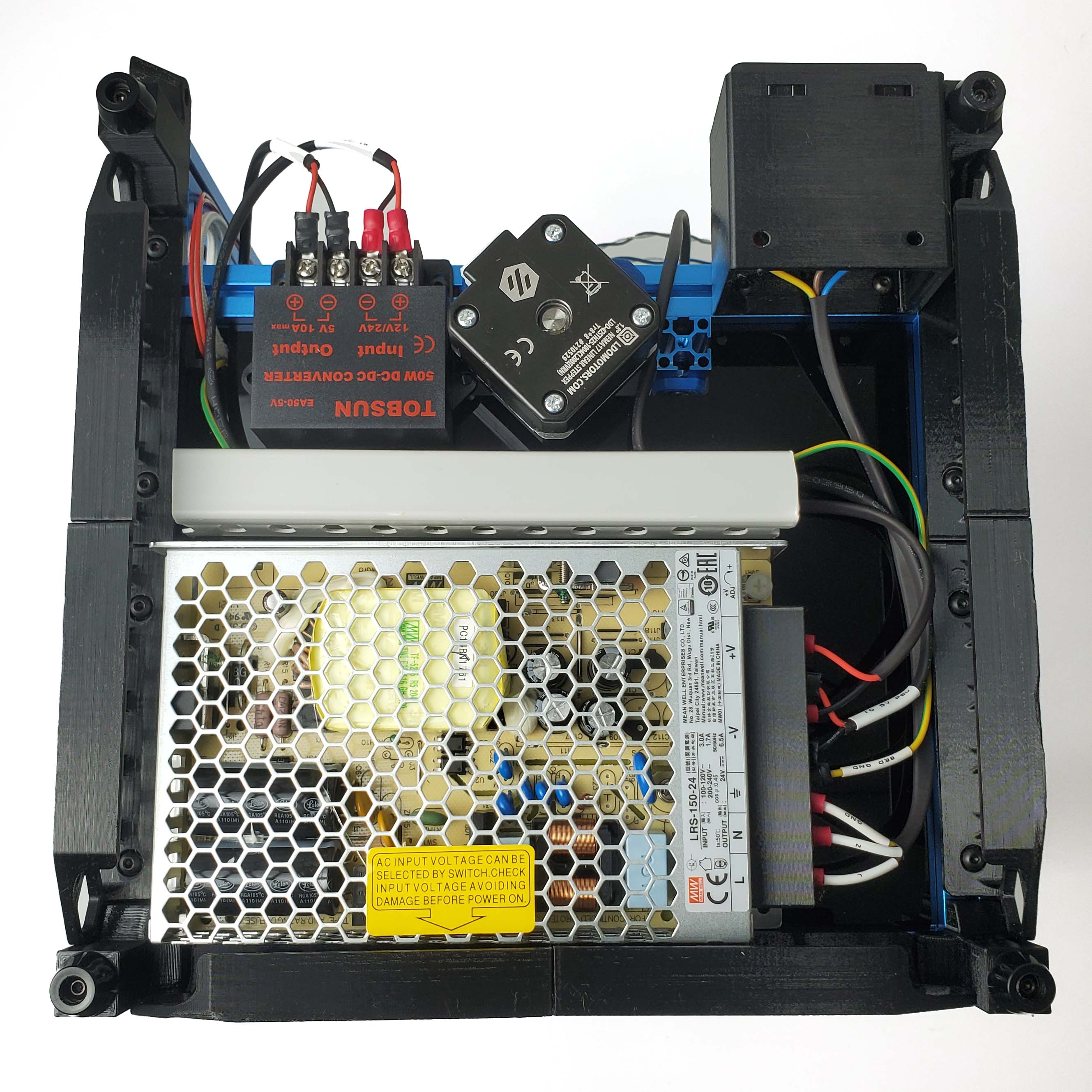
Finally, cover up the PVC duct and PSU.
¶ Wiring The Electronics
¶ Placing the Controllers
First let's place the SKR main board, Raspberry Pi, and the remaining PVC duct. Our layout is slightly different from the official assembly manual:
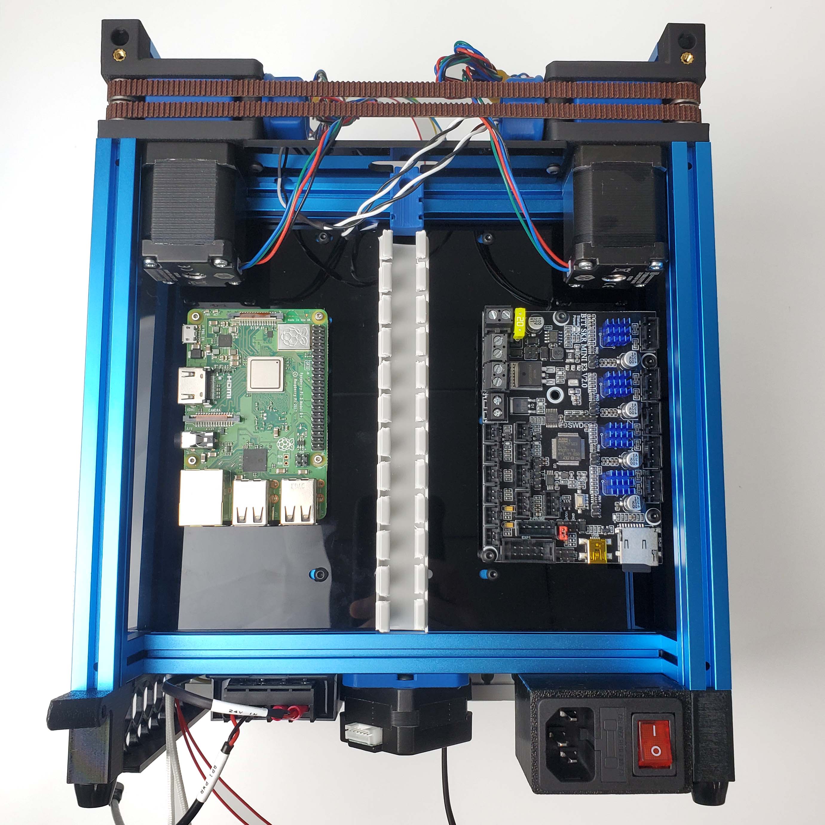
Make sure to leave enough clearance at the bottom side for the USB cable.
¶ Connecting to Power
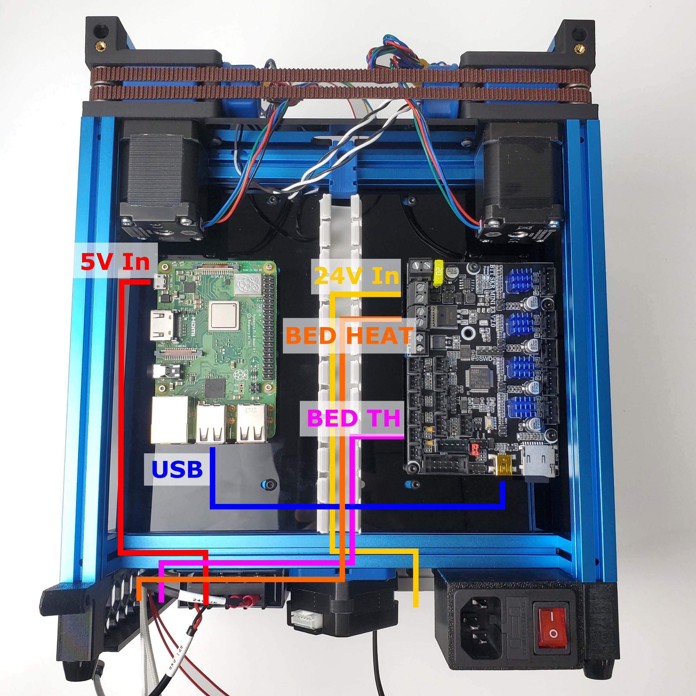
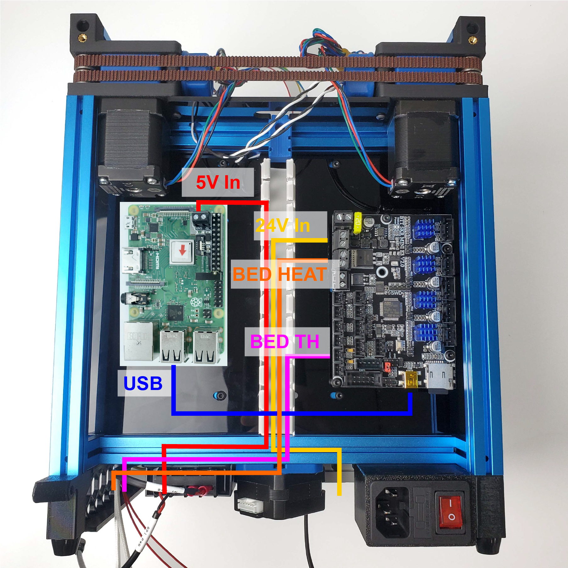
First, let's connect the power supply, the USB cable, and heatbed cables, the layout is as follows:
The power connection for the Raspberry Pi has 2 different connections depending on the kit revision.
- Using Micro USB for Rev. A/B/C
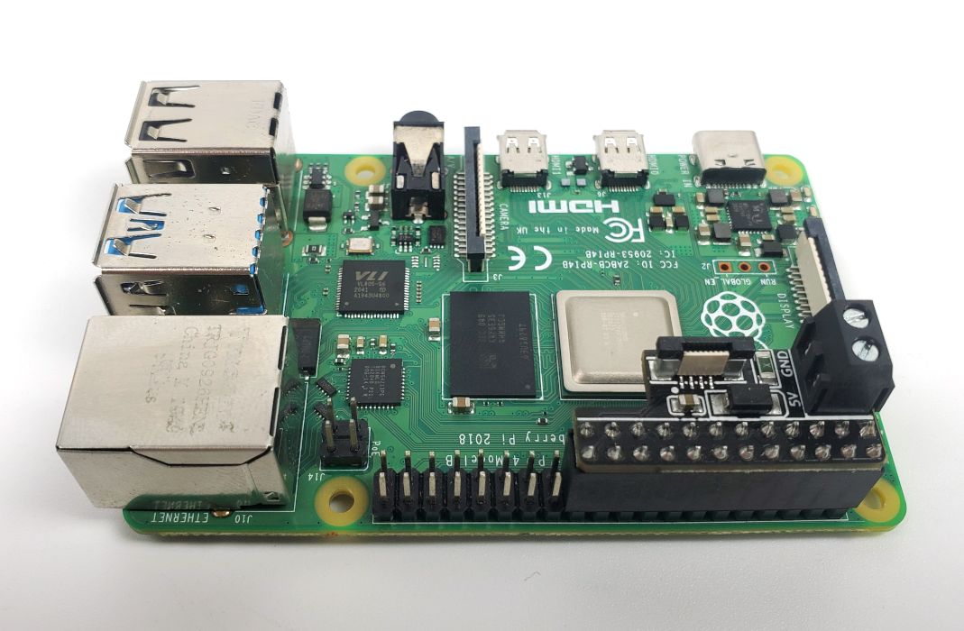
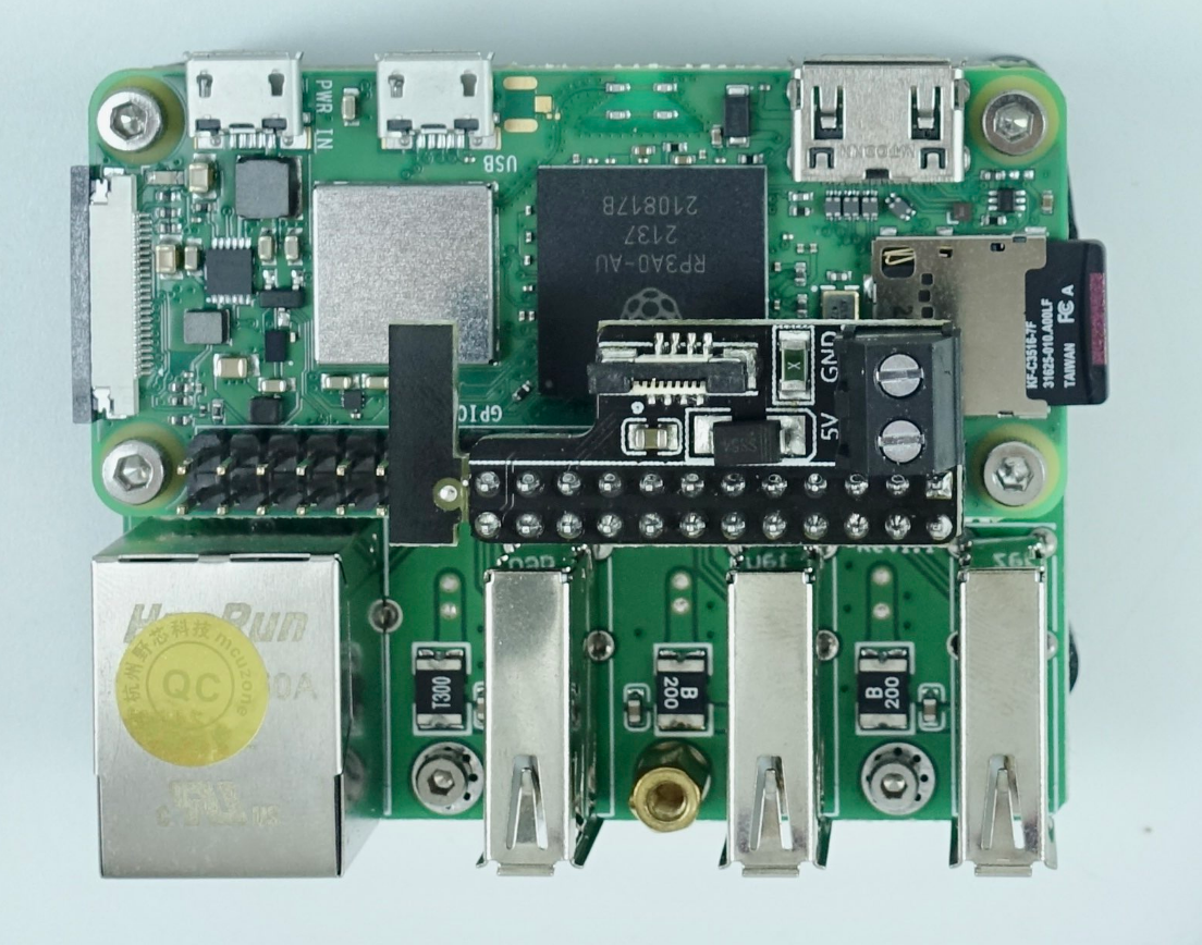
- Using GPIO connection Rev. D to the ADXL Pi PCB (ADXL not included)
|
|
Orientation for the ADXL Pi PCB (Rev. D):
|
|
IMPORTANT: Note the polarity of the screw terminal on the PCB
The result: (All following example photos will show only the Micro USB power connection for the Raspberry Pi 3B+)
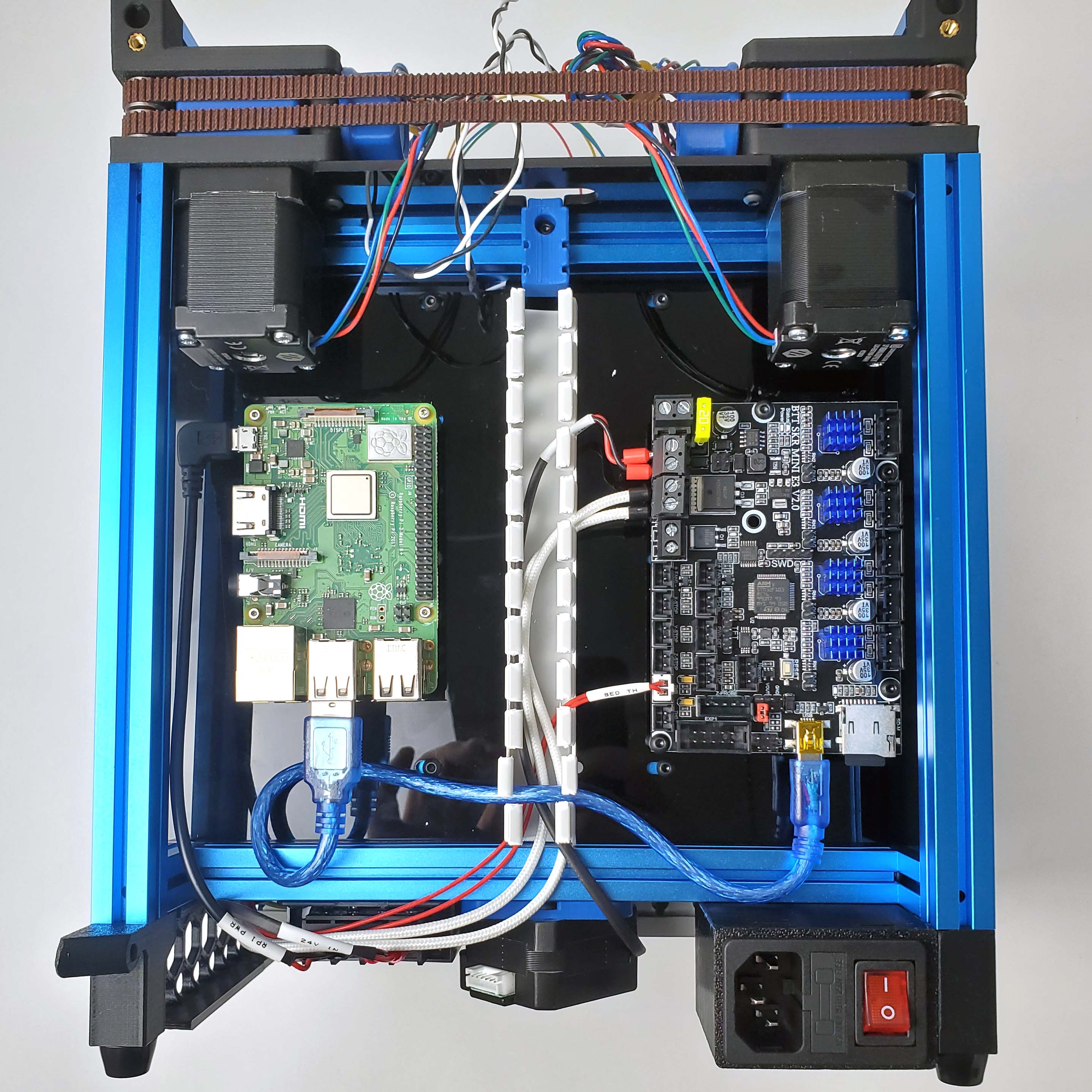
¶ Y, Z Endstops
Now connect the Y and Z Endstops, make sure that you used the cutouts reserved for each respective endstop cable in the panels.
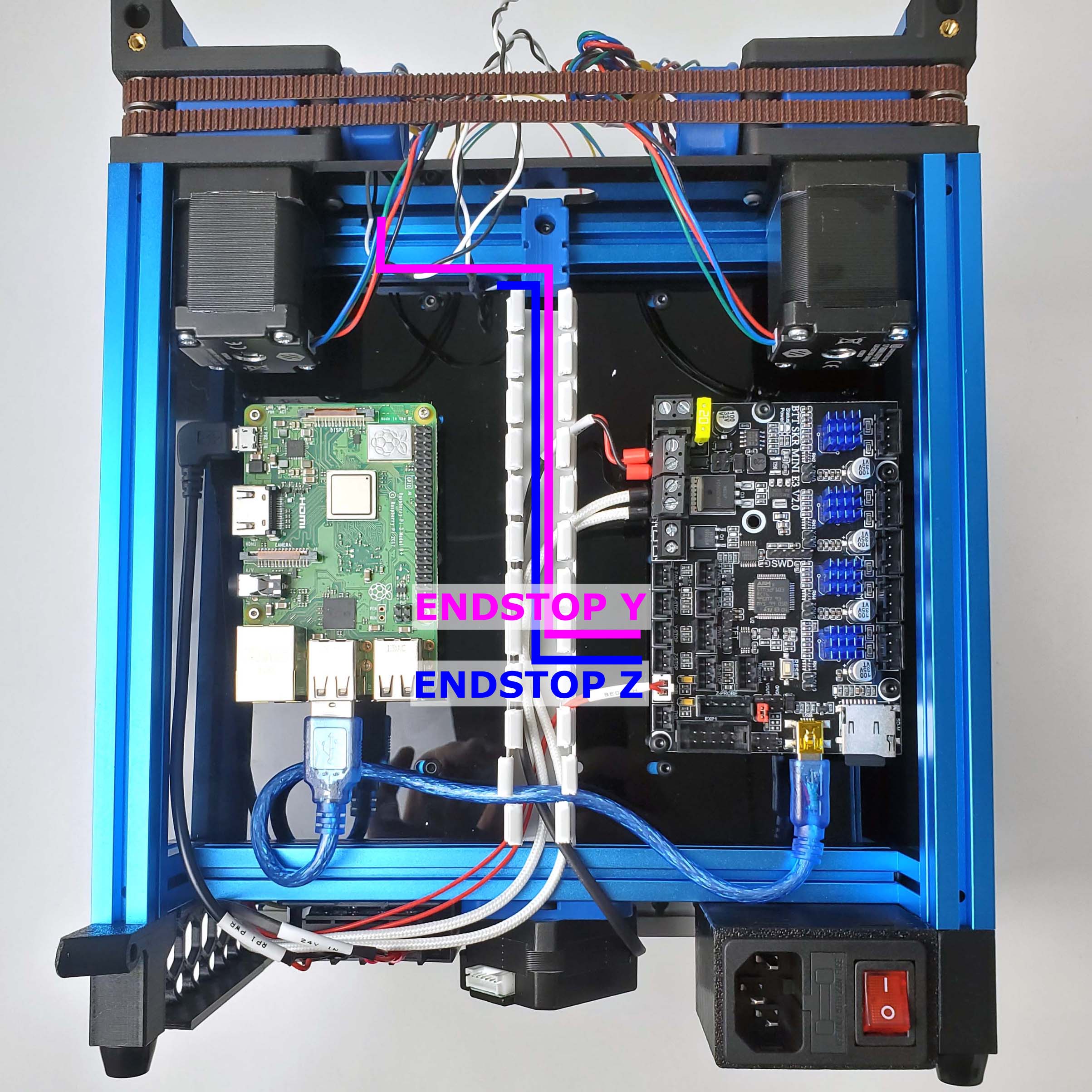
The result:
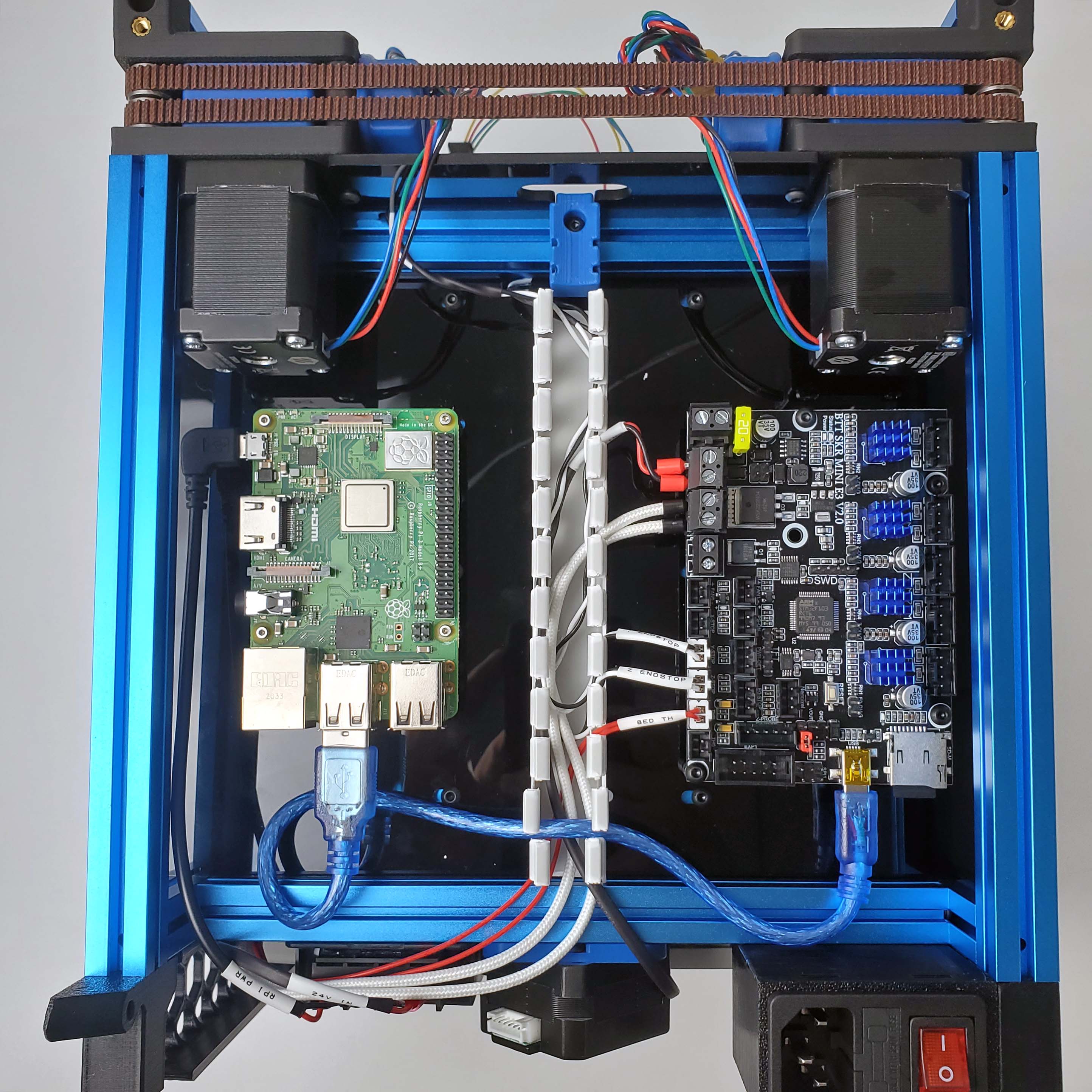
¶ Toolhead Connections
Run the bundle of toolhead cables through the motor panel and straight into the top end of the PVC duct. Our layout will look like this:
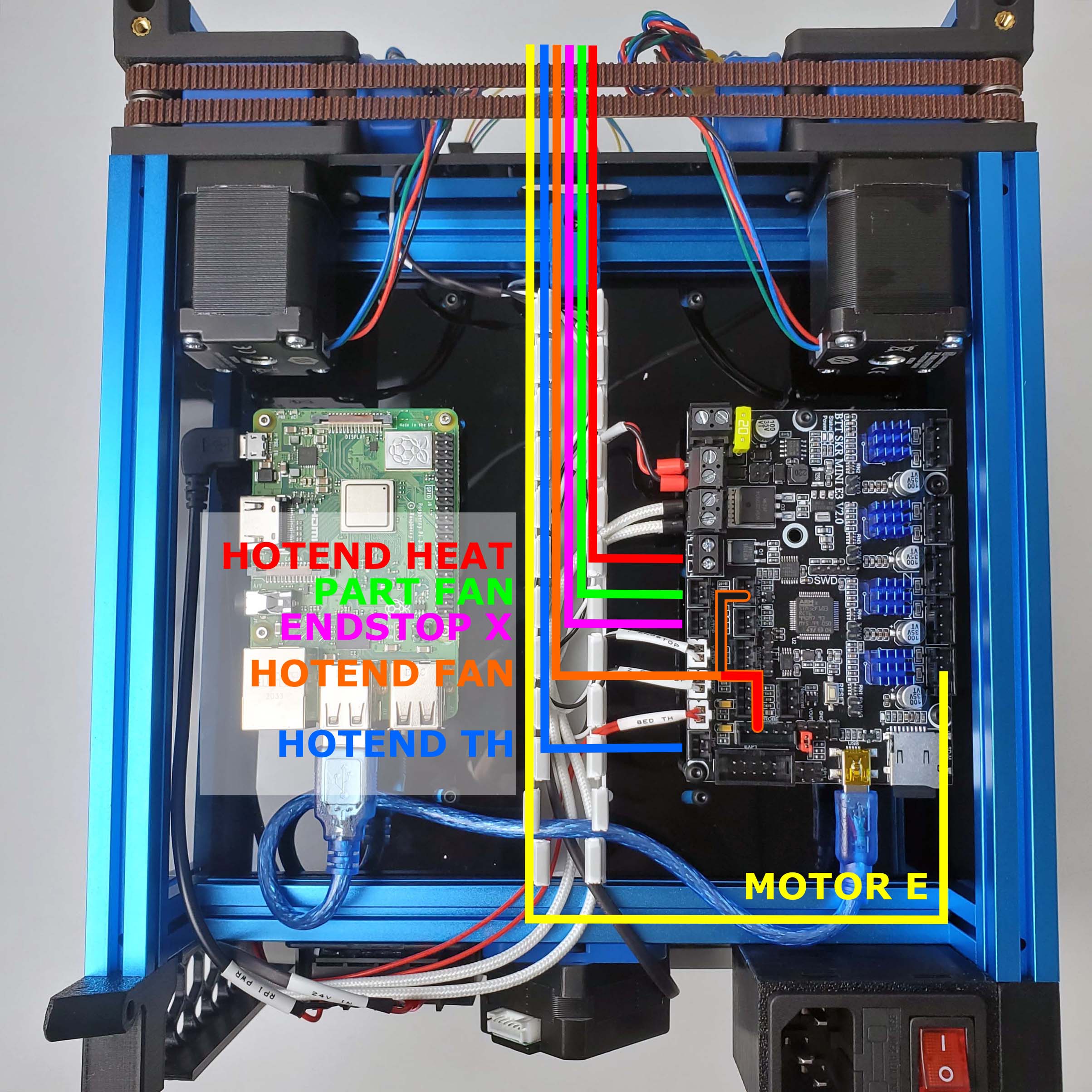
Be especially careful with the hotend fan connection, as it is easy to insert either pin into the wrong place (double check with the manual). The end result should look like this:
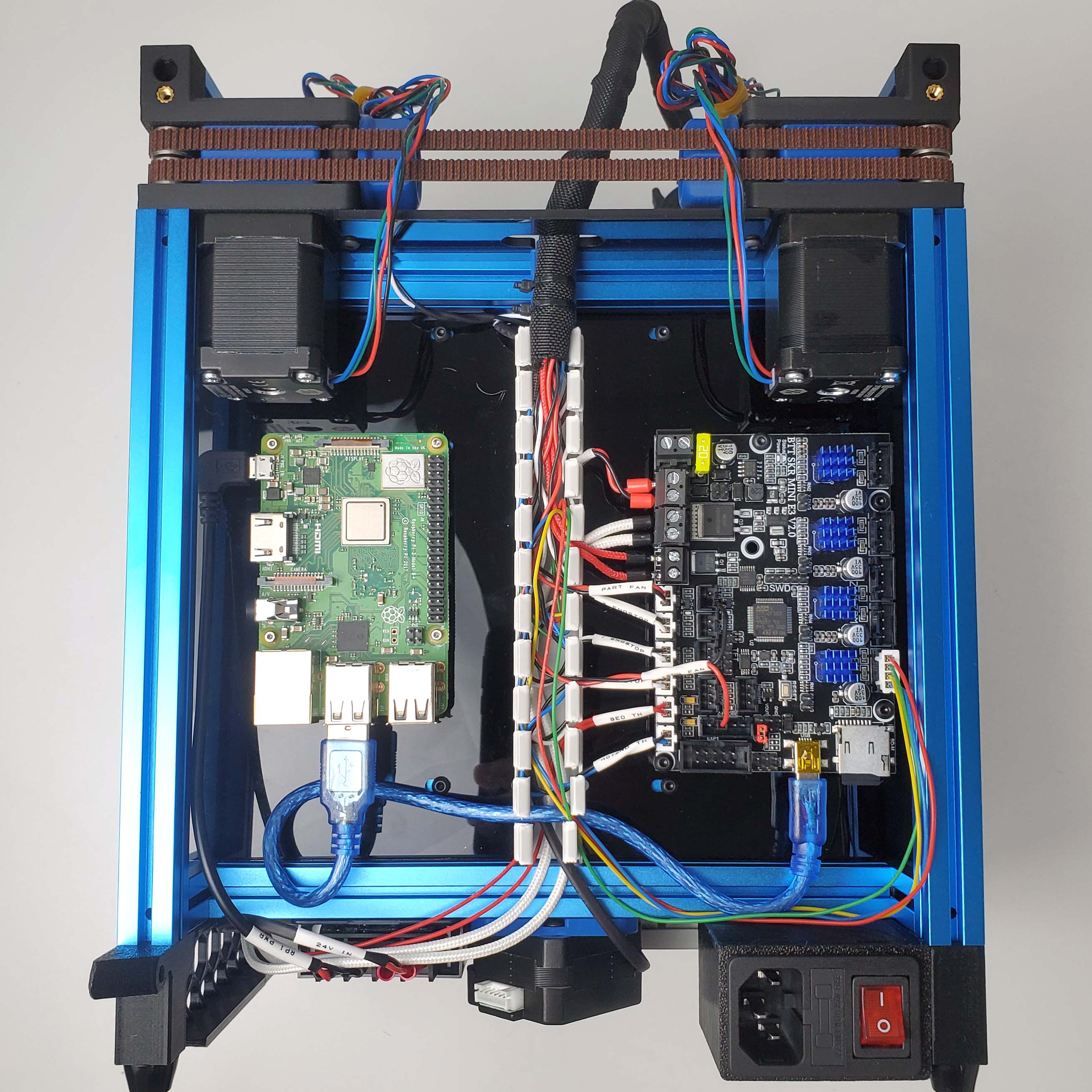
¶ A, B, Z Motors
Finally we connect the remaining motor cables. The motor cables are longer than needed, you may choose to cut them or leave them as is (we cut ours). Also don't forget the bowden tube.
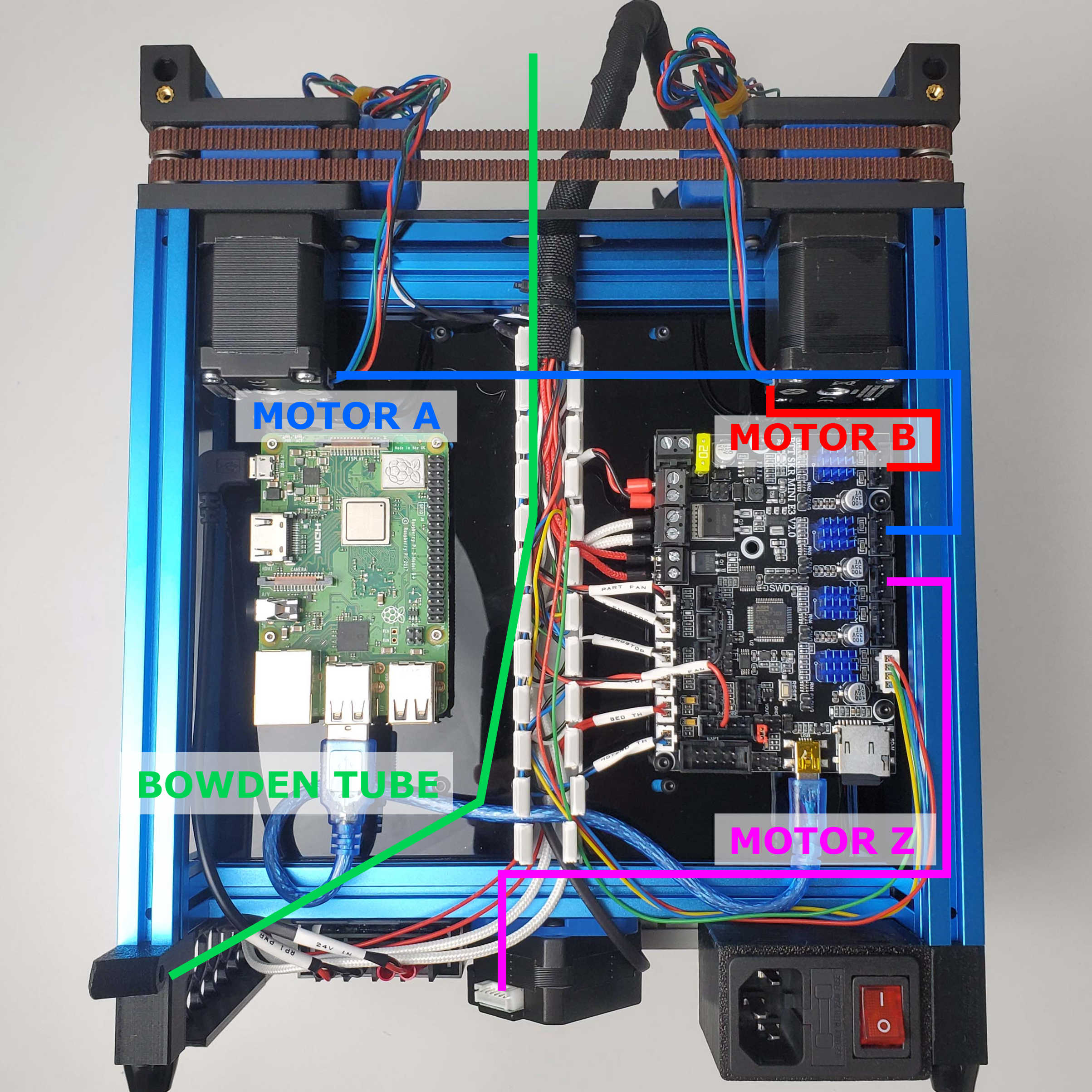
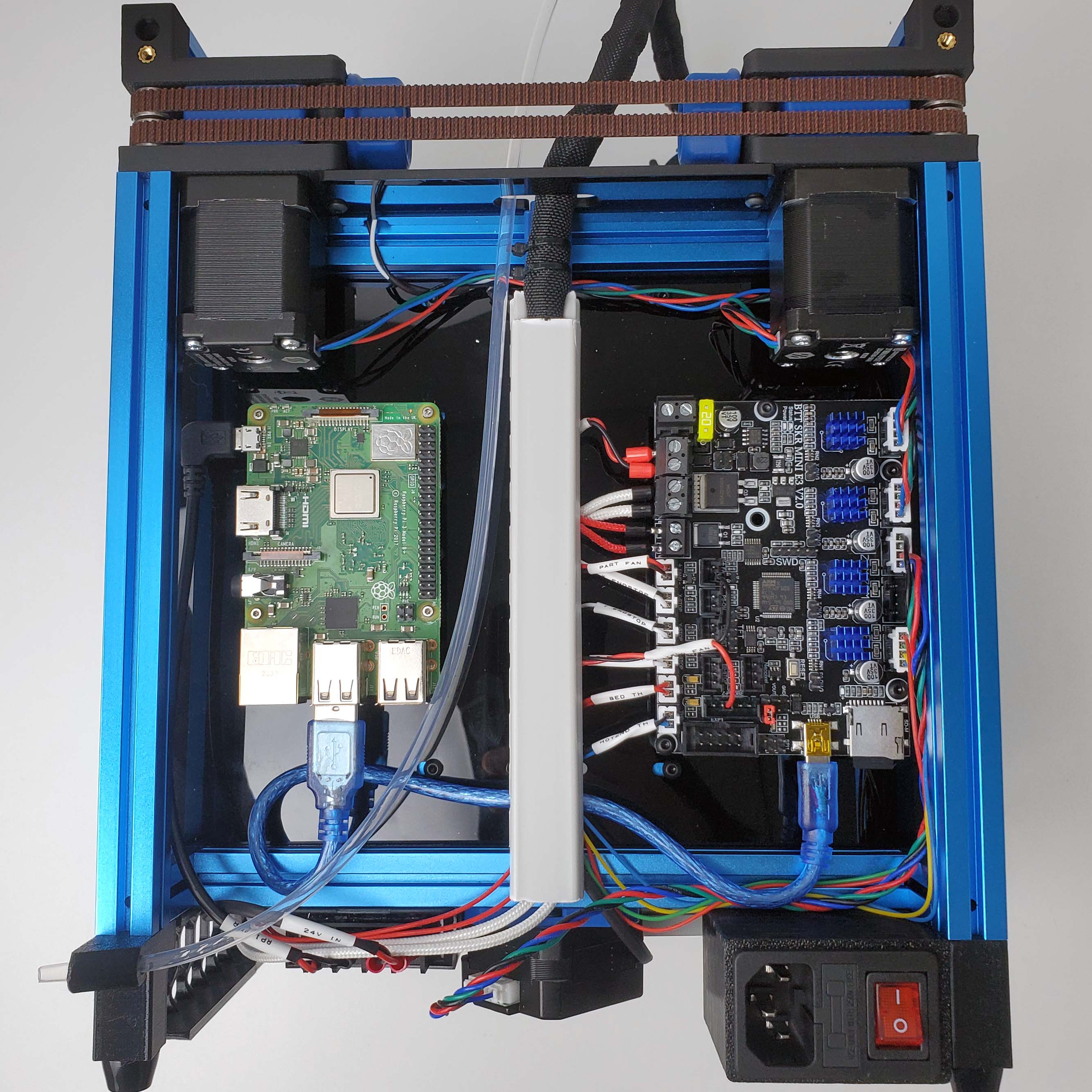
After connecting all the wires, you can now cover up the PVC duct. Wiring is now complete!
Updates:
Rev C: Removed Bed GND wire
Rev D: Add GPIO Power Wire and ADXL Pi PCB