¶ Introduction
Nitehawk-SB by LDO is a toolboard specifically designed for the Voron Stealthburner toolhead. It is a toolhead PCB featuring RP2040 MCU, TMC2209 stepper drive, ADXL345 accelerometer all integrated into one board. The form factor of Nitehawk is based on HartK’s two piece stealthburner toolhead PCB but with some minor changes.
Nitehawk uses USB communication with the RPI rather than CAN. So the software and hardware setup is far simpler and familiar to most people who have setup Klipper printers before
¶ Features
- Convenient wiring, no more complicated and error prone breakout cables - nitehawk only requires 24V power and a USB connector to the RPI host.
- USB Klipper connection, no additional software or hardware setup compared to CAN
- Custom toolhead cable, a single combined USB data and power cable rated for drag chain use, but can also be used in umbilical configuration.
- Convenient Input Shaping, run input shaper calibration at anytime with an onboard accelerometer.
- Tacho enabled fans, both hotend and part fan ports are three pin tachometer compatible, allowing for additional diagnostics and safety.
¶ System Overview
The Nitehawk system consists of three PCBs and the Umbilical Cable. A simplified wiring diagram is shown below:
- Nitehawk-SB, this is the main PCB, which houses the MCU, stepper driver, fan drivers, and other circuits.
- Fan Adapter, this is simple PCB receives the part fan, hotend fan, and neopixels and connects them to the main Nitehawk PCB via headers. The main purpose of this seperation is to allow the Stealthburner front to be easily detactable for maintenance.
- Umbilical Cable, this is a custom flex cable that is rated for drag chain use. It delivers 24V power to the main Nitehawk PCB while also carrying USB data.
- USB Adapter, this simple PCB combines 24V power from the power supply and USB data from the Raspberry Pi into a unified connection to the main Nitehawk PCB via the Umbilical cable.

¶ Printed Parts
Nitehawk-SB works with the a standard Stealthburner toolhead, and is compatible with both Clockwork 2 and Galileo 2. However a few additional custom printed parts. The printed parts are available in the Nitehawk github repo https://github.com/MotorDynamicsLab/Nitehawk-SB
- USB Adapter Mount, this is the mount for the USB adapter PCB. It is designed to be used with a standard Voron DIN clip and can be mounted in two different orientations. It also features a cover to reduce the chance of static discharge onto the PCB.
- Cable Door, this part has been slightly modified from Hartk’s original, with a zip tie anchor added for the external chamber thermistor. The door also accepts a Mx3 Captive screw so it doesn’t get lost easily when you open the door.
- Chain Anchor Tilted, This is tilts the drag chain ever so slightly to help it clear the left XY joint and also avoid rubbing the CT connector on the toolboard.
¶ Klipper Config Files
A Klipper Configuation can be found in the Nitehawk-SB github repo here. Remember to comment out tachometer_pin and tachometer_ppr configurations if you do not plan to use a tachometer enabled fan.
¶ Part Fan Check Macro
Provided in the github repo is an optional tacho_macros.cfg file which contains the macro PREFLIGHT_CHECK. This macro very briefly turns on the part fan and checks the tachometer signal to see if the fan is spinning properly. To use the macro, [include tacho_macros.cfg] in printer.cfg and call PREFLIGHT_CHECK at the beginning of the PRINT_START macro
¶ Port and Pin Definitions
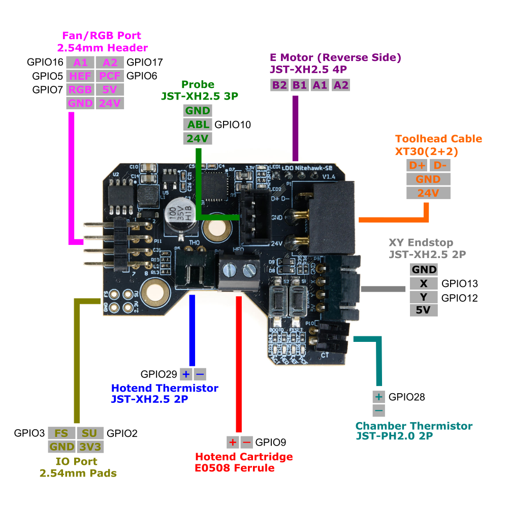
| Device/Port | PCB Label | Connector Type | RP2040 Pin | Description |
| X/Y Endstop | Endstop | JST-XH 4P | gpio13/12 (X/Y) | Connects to the X and Y dndstop. X endstop is gpio13 and Y endstop is gpio12. |
| Hotend Heater | HE0 | Screw Terminal / E0506 | gpio9 | Connects to the hotend heater. |
| Hotend Thermistor | TH0 | JST-XH 2P | gpio29 | Connects to the hotend thermistor. Uses a 2.2kΩ pull up resistor. |
| Part Cooling Fan | PCF (Fan adapter PCB) | JST-PH 3P | gpio6/17 (fan/tacho) | Connects to part cooling fan (via the fan adapter PCB). The fan control pin is gpio6 and the tachometer sensor pin is gpio17. |
| Hotend Fan | HEF (Fan adapter PCB) | JST-PH 3P | gpio5/16 (fan/tacho) | Connects to hotend fan (via the fan adapter PCB). The fan control pin is gpio5 and the tachometer sensor pin is gpio16. |
| Chamber Thermistor | CT | JST-PH 2P | gpio28 | Chamber Thermistor port. Connects to an external thermistor. Uses a 4.7kΩ pull up resistor. |
| Probe | PROBE | JST-XH 3P | gpio10 | Probe for bed leveling and/or Z sensing. 24V power only. |
| Motor | MOTOR | JST-XH 4P | gpio23/24/25/0/1 (step/dir/ena/uart/tx) | A stepper motor port for the extruder. Driven by a TMC2209 chip. The current sense resistor is 100 mΩ. Enable is active low |
| Neopixel | LED (Fan adapter PCB) | JST-PH 3P | gpio7 | Connects to neopixel LEDs (via the fan adapter PCB). |
| Activity LED | ACT | N/A | gpio8 | A small software controlled onboard LED. Active low. |
| Accelerometer | N/A | N/A | gpio21/18/20/19 (cs/clk/mosi/miso) | ADXL345 accelerometer for input shaping. Controlled via software SPI. |
¶ Pinout: Fan Adapter PCB
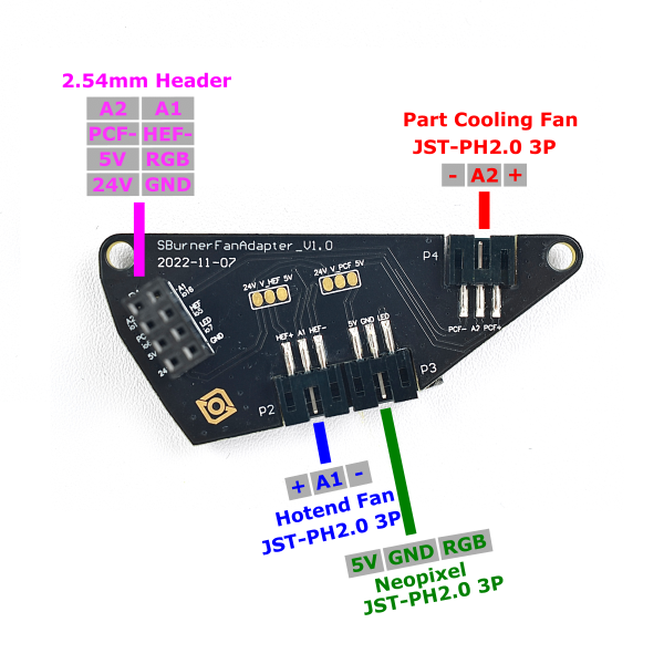
The table below briefly describes the purpose of each port located on the toolhead PCB.
| PCB Label | Name | Connector | Description |
| HEF+/A1/HEF- | Hotend Fan* | JST-PH-3P | Fan port for cooling the hotend heatsink. 24V/5V selectable, defaults to 24V. |
| PCF+/A2/PCF- | Part Cooling Fan* | JST-PH-3P | Port for part cooling fan. 24V/5V selectable, defaults to 24V. |
| 5V/GND/LED | Neopixel | JST-PH-3P | For connecting to the neopixel chain on the stealthburner. |
| Toolhead Cable | 2x8 F-Header | Plugs into the male header on the main toolhead PCB |
*The hotend fan and part fan can be independently changed to 5V in two steps:
- Severe the 24V connection by cutting the trace between the 24V pad and V_HEF/V_PCF pad
- Make a soldered bridge connection between the 5V pad and V_HEF/V_PCF pad
¶ Electrical Specifications
| Parameter | Symbol | Minimum | Typical | Maximum | Unit | Comments |
| Power Supply Input | Vin | 20 | 24 | 28 | V | power input for the toolboard |
| 5V Current | Irpi | 5 | A | current output for the 5V buck converter | ||
| Fan Current(HEF, PCF) | Ifan | TBD | A | current rating for each fan port (HEF and PCF). | ||
| Hotend Current | Ihe | TBD | A | limited by max. continuous current of mosfet |
¶ Firmware Setup and Update
The firmware for Nitehawk consists of two components: Katapult and Klipper. Katapult is a bootloader designed specifically for Klipper, it ensures that the software on the RP2040 MCU boots up smoothly and allows for easy updating of the Klipper firmware. You can learn more about Katapult here. Klipper is the main firmware that runs on the RP2040 MCU, you can learn more here.
Your Nitehawk will come shipped with both Katapult and Klipper installed. Ideally, you will only ever need to occasionally update the Klipper firmware and never have to touch Katapult. If the Katapult bootloader was erased or is not present for any reason, you can check this section for instructions on how to reupload Katapult.
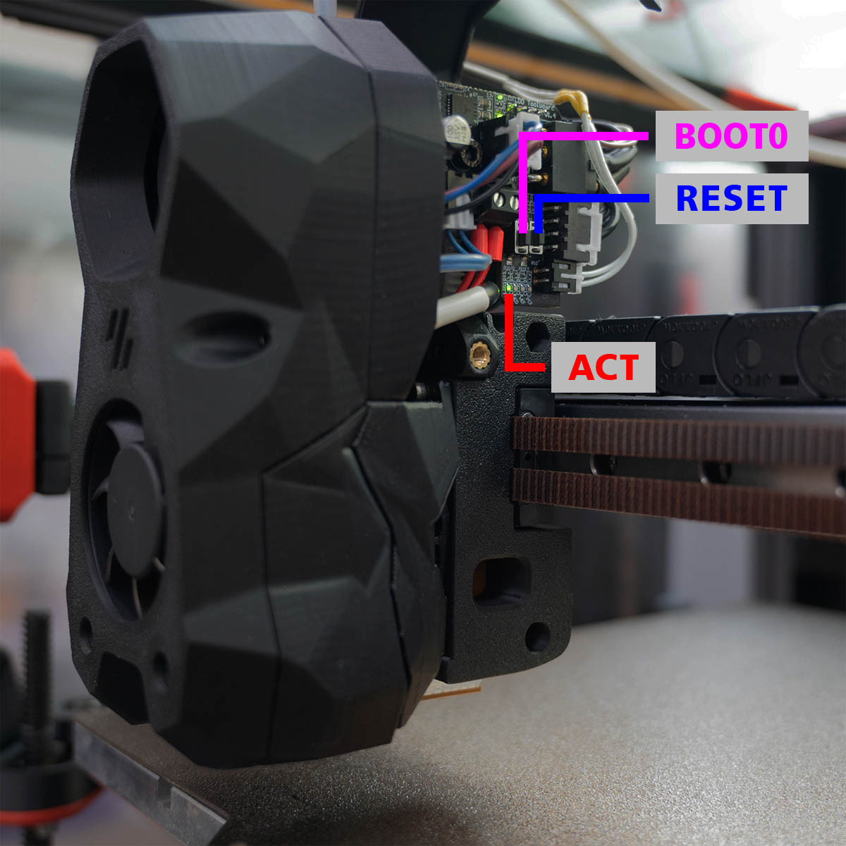
¶ Hardware Setup
No special setup is required for installing either Klipper or Katapult. Nitehawk simply needs to be hooked up as it operates normally in your 3D printer, with the toolboard connected to your Klipper host device (e.g. Raspberry Pi) via the USB adapter board. You also need access to the two buttons (RESET and BOOT0) on the toolboard, this is normally done by moving the toolhead to the front and opening the toolhead cover. Also note the four LEDs below the buttons - the leftmost LED is the ACT indicator light, which will be important later. Reference the photo below to find the buttons and LEDs.
¶ Compiling Klipper Firmware
The following instructions are for compiling and upload new Klipper firmware to your Nitehawk toolboard. You need to perform these steps if you want to update your klipper firmware to the newest version or if you are doing a fresh install and just uploaded Katapult (see the previous sections). Before compiling the firmware, you will need to have Klipper already installed on your host device (e.g. Raspberry Pi).
- Log on to your Klipper host via SSH, windows users can use putty or any other SSH client. Mac and Linux users can simply connect with the
sshcommand in their command line terminal. Run the following commands to open the firmware configuration interface:
cd ~/klipper
make menuconfig- In the configurator, Enable extra low-level configuration options, choose Raspberry Pi RP2040, match the rest of the settings with the screenshot below:
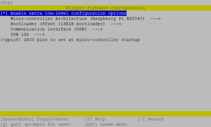
- Most importantly, make sure you set the
16KiB bootloaderoffset. Otherwise you will erase the Katapult bootloader! - Enter
Qto quit and confirm withYes when prompted to save. And run the following to generate the firmware file:
make clean
make- A firmware file called will now be generated and can be located in the directory
~/klipper/out. You are now ready to upload this firmware to the Nitehawk toolboard. The recommended method is uploading via themake flashcommand.
¶ Uploading Klipper (via make flash)
- Run
ls /dev/serial/by-idto find the USB ID of your Nitehawk toolboard. The USB ID should have a format similar to this:usb-Klipper_rp2040_1234567890000000-if00. - Run the following commands. This will install the
python,pip, and thepyserialpython module if it is not present. You may receive anerror: externally managed environmentwhen running the last command. This simply meanspyserialhas already been installed and you may move on to the next step.
sudo apt install python3 python3-pip
pip install pyserial- Run the following commands to upload the firmware to the MCU directly:
cd ~/klipper
sudo service klipper stop
make flash FLASH_DEVICE=/dev/serial/by-id/<your USB ID>
sudo service klipper start- If you encounter any connection issues after flashing the new firmware, reboot your printer. Your frame PCB should now have the newest firmware. If the flashing process failed, you may want to try using the the second method and upload Klipper via Katapult
¶ Uploading Klipper (via Katapult)
In this section we will use an alternative method to upload klipper firmware using the Katapult bootloader. If your toolboad is missing the Katapult bootloader for any reason, you should follow the next section to install it first.
- First we will check and install the Katapult package (if necessary):
test -e ~/katapult && (cd ~/katapult && git pull) || (cd ~ && git clone https://github.com/Arksine/katapult) ; cd ~- To upload Klipper, we will use a Python script to communicate with the Katapult bootloader inside of the Nitehawk Toolboard. First, we will first need to setup a Python3 environment. Run the following:
virtualenv -p python3 ~/katapult-env
~/katapult-env/bin/pip3 install pyserial- This creates a Python 3 environment in the location
~/katapult-env/and installs the modulepyserialwhich is required to run the upload script. - Now we must force Nitehawk to enter the Katapult bootloader and obtain the USB serial address. Start by quickly double clicking the RESET button, you should see the ACT light blinking slowly.
- Next run
ls /dev/serial/by-id/. You should see something likeusb-katapult_rp2040_A1234567898D1234-if00- note that the address contains the wordkatapult. If not, this means either your Nitehawk did not have Katapult installed or you did not enter the Katapult bootloader properly. Copy the address down for the next step, do not exit the bootloader yet. - Finally run the following but substituting the address with the one you obtained in the previous step. If everything was correct, you should see some write and verification progress followed by
Flash Successat the end.
~/katapult-env/bin/python3 ~/katapult/scripts/flashtool.py -d /dev/serial/by-id/usb-katapult_rp2040_A1234567898D1234-if00- As a finally verification, run
ls /dev/serial/by-id/. you should see a Klipper USB serial address in the form ofusb-Klipper_rp2040_E1234567A12D9835-if00.
¶ Installing the Katapult Bootloader
In this section we will compile and upload the Katapult Bootloader. Note that your Nitehawk toolboard normally ships with Katapult pre-installed and you only need to perform the following operations if Katapult was inadvertently overwritten or lost.
- Login to the Raspberry Pi. We will check and download the Katapult package (if necessary):
test -e ~/katapult && (cd ~/katapult && git pull) || (cd ~ && git clone https://github.com/Arksine/katapult) ; cd ~- Now we will configure need to configure some options:
cd ~/katapult
make menuconfig- This will bring us to the configuration menu. Make sure to set the options as below:
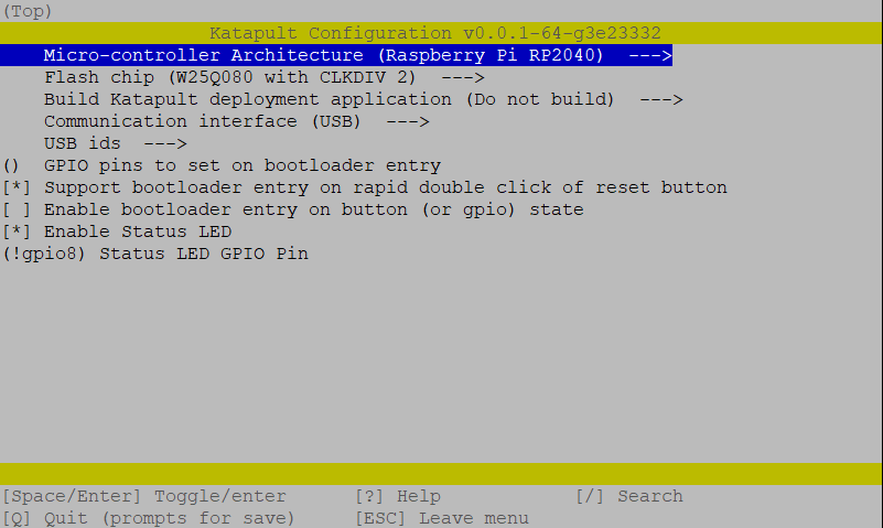
- Enter
Qto quit and confirm withYes when prompted to save. next run the following command to compile and generate the Katapult binary files:
make clean
make- A binary file called
katapult.uf2will now be created in the location~/katapult/out/. Our next job is to upload this file into the RP2040 MCU on the Nitehawk toolboard. - We now need to reboot the Nitehawk toolboard into system boot mode. This is done in three steps:
- Press and hold both the RESET and BOOT0 button.
- Release the RESET button
- Release the BOOT0 button
- If done correctly, your Nitehawk should now have entered boot mode and become a sort of semi “thumbdrive”. Run the command
ls /dev/sda*to confirm. You should see something like/dev/sda/ dev/sda1. If you get something likels: cannot access '/dev/sda*': No such file or directorythis means either Nitehawk didn't enter boot mode or there is a problem with the physical connection between the Raspberry Pi and Nitehawk. - We are now finally ready to upload Katapult. Run following commands:
sudo mkdir -p /mnt/pico
sudo mount /dev/sda1 /mnt/pico
sudo cp ~/katapult/out/katapult.uf2 /mnt/pico
sudo sync
sudo umount /mnt/pico- The above commands basically mount the Nitehawk as a storage drive and copies the katapult binary files into that drive. It then unmounts the drive. If everything went smoothly, you should now be able to see the ACT light located below the BOOT0 button blink slowly. To double check that Katapult is installed, run
ls /dev/serial/by-id. You should see something like:usb-katapult_rp2040_A1234567898D1234-if00which is USB serial address of Nitehawk running Katapult. A few small details to note here:
- You will only see this address when Nitehawk is in Katapult bootloader mode and not in system boot mode or when Nitehawk is normally running Klipper.
- You can force Nitehawk to enter the Katapult bootloader by quickly double clicking the RESET button on the toolboard. The ACT light blinks slowly in this mode as previously mentioned.
- You will need enter the Katapult bootloader and the Katapult USB serial address to upload Klipper.
- By following the above instructions, you will have uploaded Katapult but erased all other firmware, including any previously installed Klipper firmware.
- Exit the Katapult bootloader by single pressing the RESET button, normally you would enter Klipper firmware. Since you just erased Klipper, you will just re-enter the Katapult bootloader.
- you are now ready to compile and upload Klipper - see the previous section here.
¶ FAQ
Q. I have an LDO V2.4/Trident Kit, the fan adapter PCB provided looks identical to the one in the kit are they interchangeable?
A. Yes! The fan adapter PCB is 100% the same as the one in the current LDO kits.
Q. Can I use the provided cable in a drag chain or umbilical setup?
A. Yes! The included toolhead cable is drag chain rated but also easily set up for umbilical use.
Q. I see that there is a 4pin XY endstop connector, what is that for?
A. Since there is no longer any breakout PCB, the XY endstop can instead be routed a short distance through the X drag chain and into the toolboard. Of course, you can also opt to route directly back to the mainboard or just use sensorless homing.
Q. What is the ACT LED for?
A. That’s just a controllable LED, you can find it in the klipper config we provide. It doesn’t do anything else otherwise.