For Micron build, please refer to the official manual.
This guide contains directions for wiring a LDO Micron Plus Kit using the pre-cut, pre-terminated cables included in the kit. Important! Mains wiring should only be performed by certified personnel trained in local regulations and safety standards.
¶ Tools
Here is a short list of tools you should prepare:
- 2.5mm slot head screwdriver (not included in kit), This screwdriver is used to manipulate the plug type terminals.
- Phillips screwdriver (not included in kit), This screwdriver is used on the power supply and SSR.
- 2.0mm hex driver (included in kit), This screwdriver is used to tighten screws.
- Multimeter (not included in kit), Used to check connectivity.
¶ Above Deck Wiring
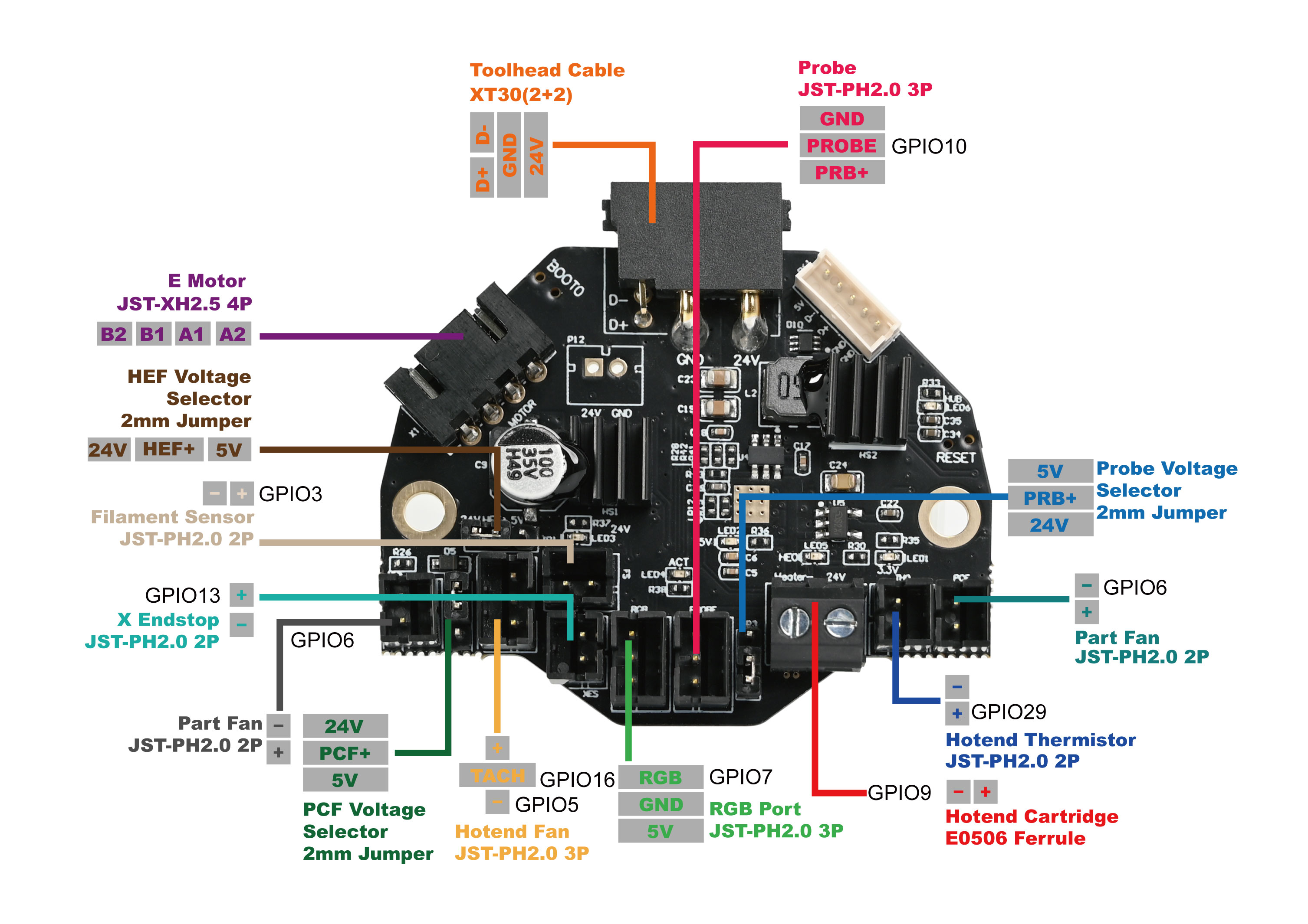
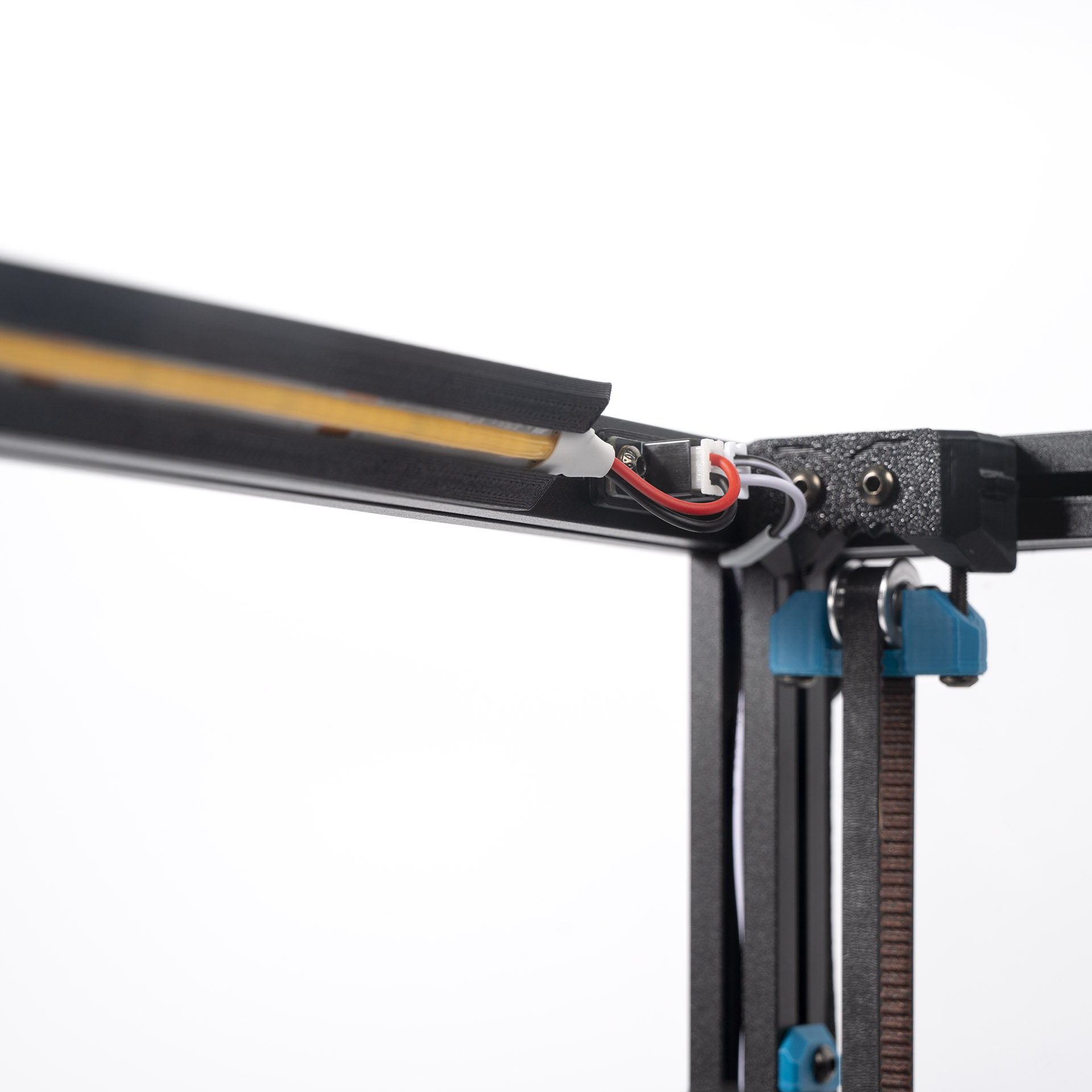
¶ Wiring the Toolhead PCB
- Connect the hotend heater/cartridge to the screw terminal connector - polarity does not matter here. If you have a hotend with a integrated heater element, you may need to crimp ferrules onto the heater cables. The ferrule type to use is E0506.
- Connect the hotend thermistor to the TH0 port. A thermistor is not provided in the kit (Semitec 104NT); if you have a hotend with a integrated thermistor, you may need to crimp a connector on the thermistor cable. The connector type to use is JST-PH2.0 two pin
- Connect two PCF cables (labelled PCF) to the Part Fan ports.
- Connect the Klicky cable (labelled Klicky) to the PROBE port.
- Connect the RGB cable (labelled RGB) to the RGB port.
- Connect filament sensor cable (labelled FS1) to the FS port.
- Connect filament sensor cable (labelled FS2) to the XES port.
- Connect the the cable of the hotend fan (labelled HEF) to the Hotend Fan port.
- Connect the extruder motor to the E MOTOR port.
- Attach the Toolhead cable to its port - you can do this after installing the extruder onto the X carriage.
¶ Wiring the Bed Aux Umbilical PCB and Bed Heater
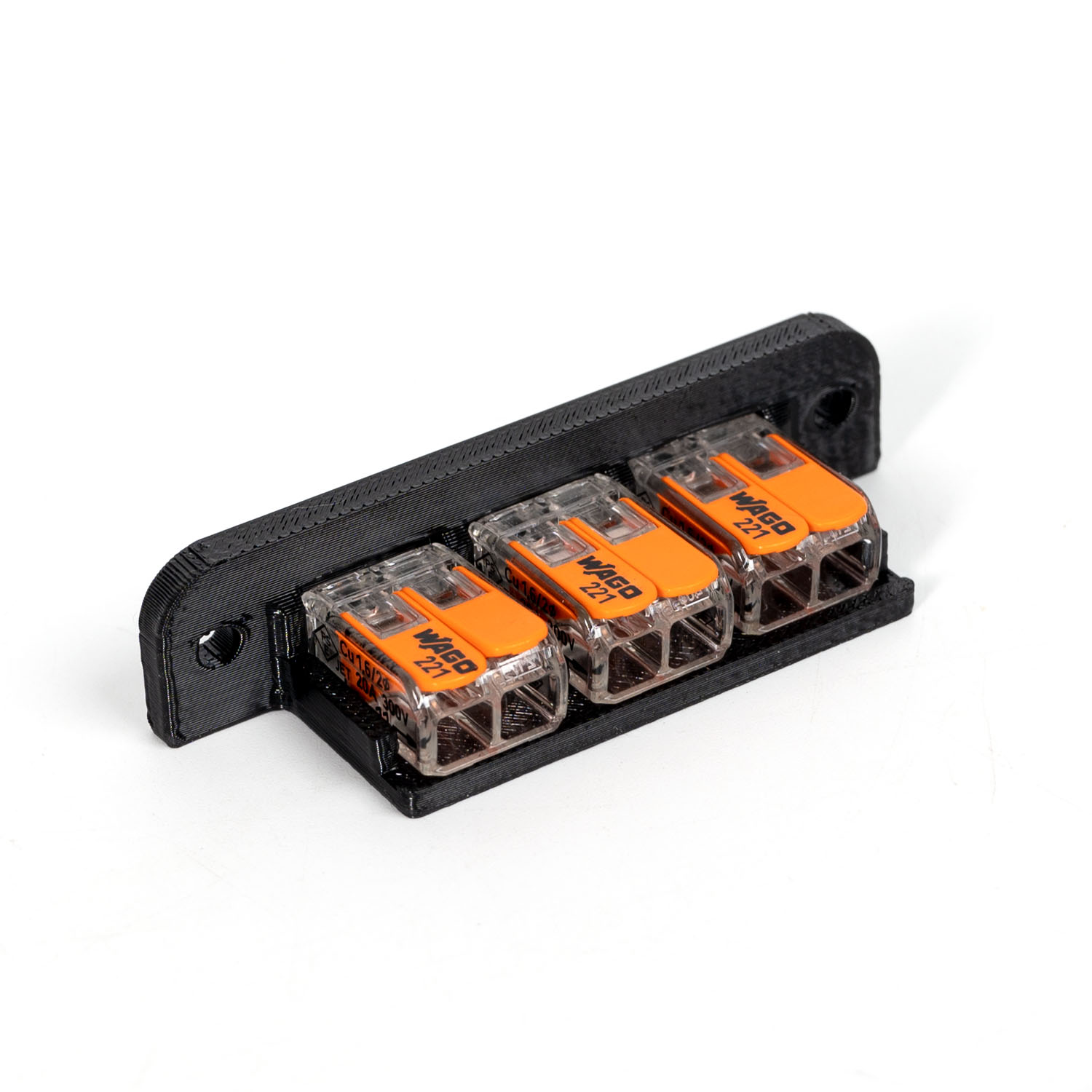
Start by assembling the bed WAGO mount. The printed part can found here. The three WAGO terminals are snapped into the printed part directly. It will be installed onto the printer using two M3 hex nuts and M3x8 BHCS screws.
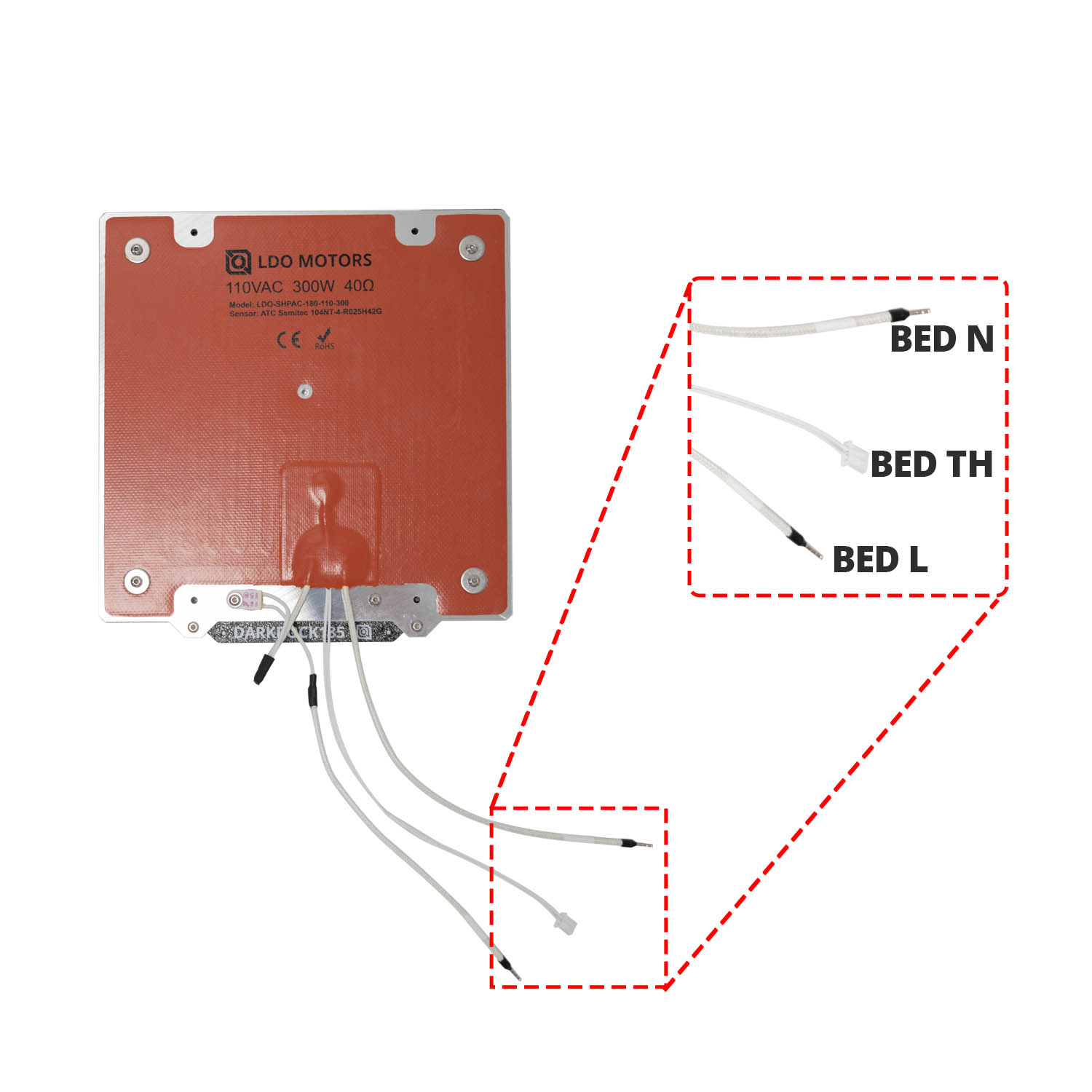
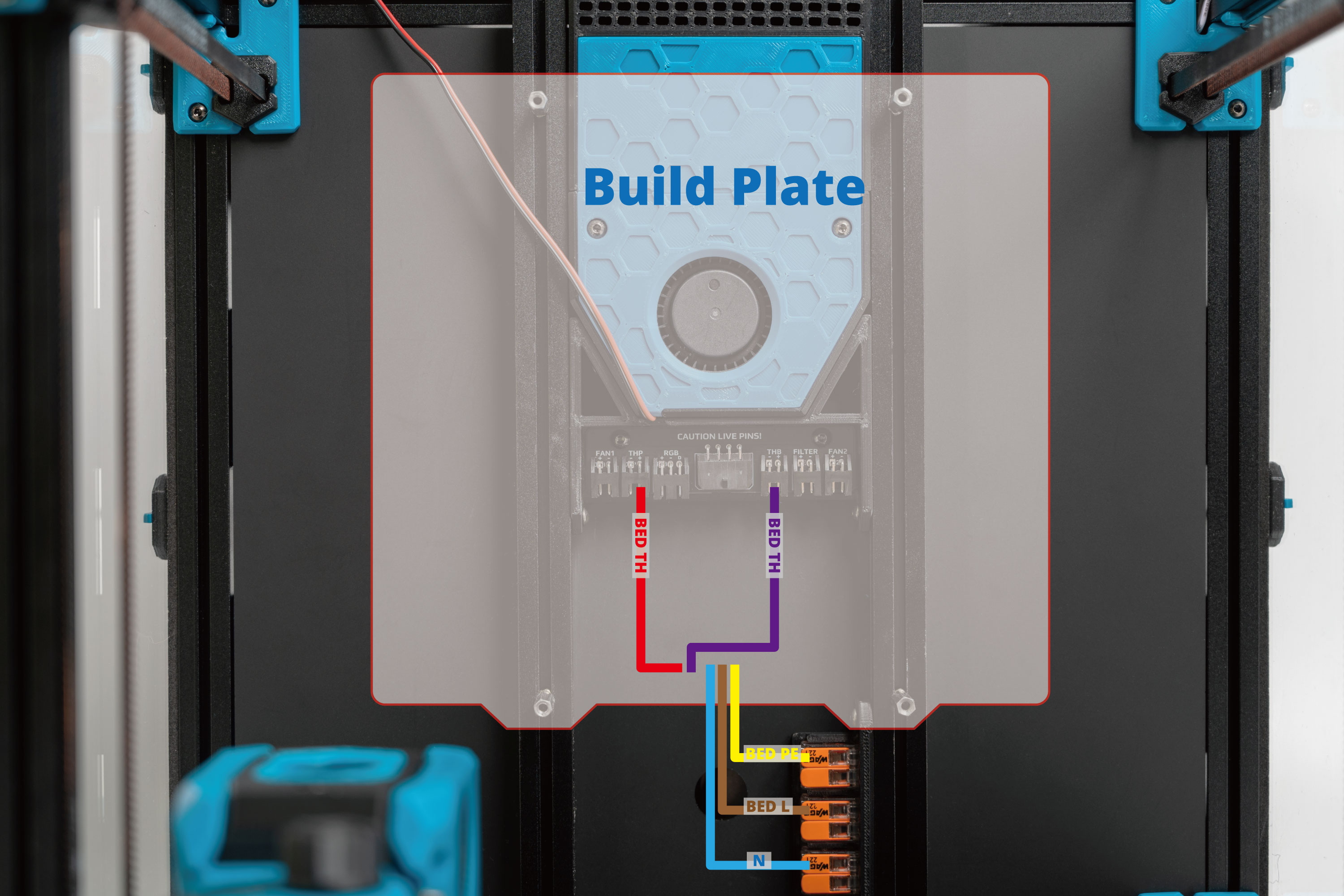
Let's first take a look at the build plate assembly. The two thick braided cables are the bed power lines (labelled N and Bed L). The thinner two pin cable is the bed thermistor (labelled BED TH).
Shown below is the overall wiring layout for the build plate.
Note:
1. One of the two bed thermistor cables is pre-assembled in the build plate and the other screw type thermistor cable needs to be installed to the build plate by users.
2. Connect the 90mm BED PE cable to the screw on the build plate.
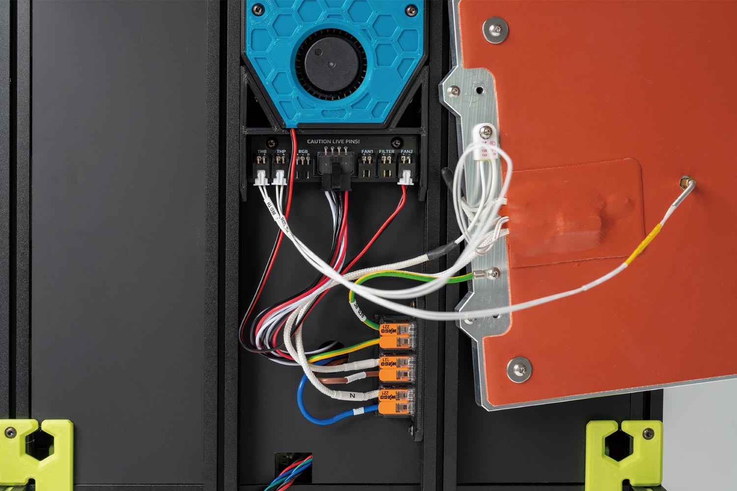
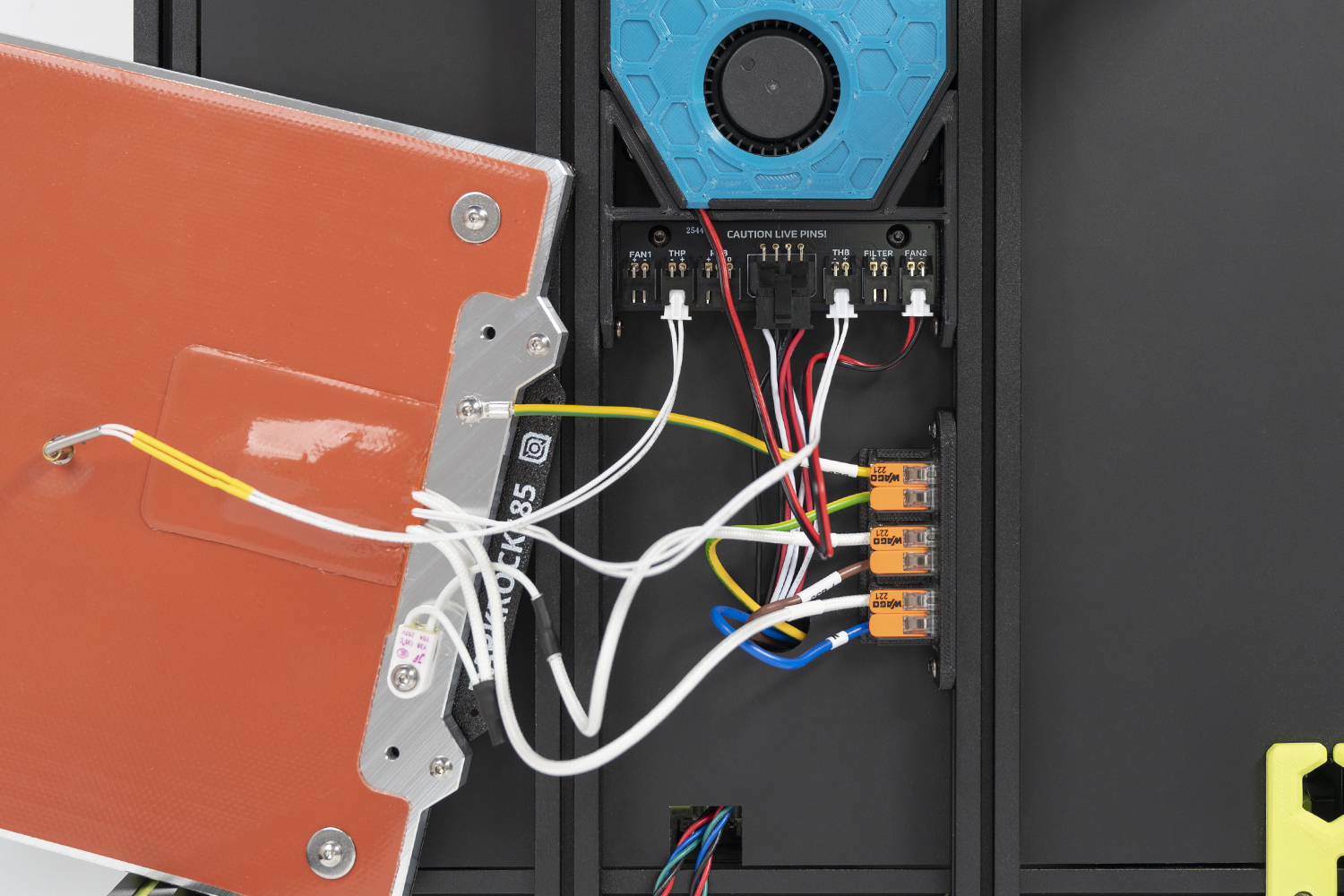
3. Starting from the second batch, the THB and FAN1 positions on the Bed Aux Umbilical PCB have been swapped.

Please refer to below image if you receive second batch PCB.
Shown below is the overall wiring layout for the Bed Aux Umbilical PCB and the WAGO terminals.
Note: Follow the routing path shown in the image and leave the other ends through the round hole. We will connect them in later steps.
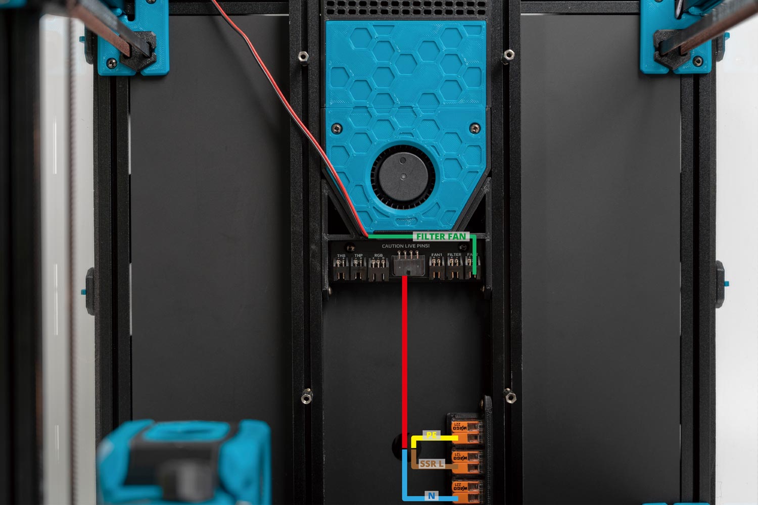
The end result should look like this:
Please refer to below image if you receive second batch PCB.
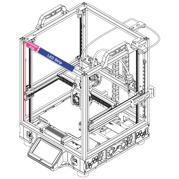
¶ Routing the LED strips
Our kit includes one COB LED strip. Remember to print the part to prevent a short with the extrusion and mount using M3 hex nuts and M3x8 BHCS screws.
We recommend following the routing path shown in the diagram below:
¶ Below Deck Wiring
¶ Preparing the Inlet
Your kit should include a pre-wired AC inlet. Double check that the wiring is correct, the final layout should be as follows:
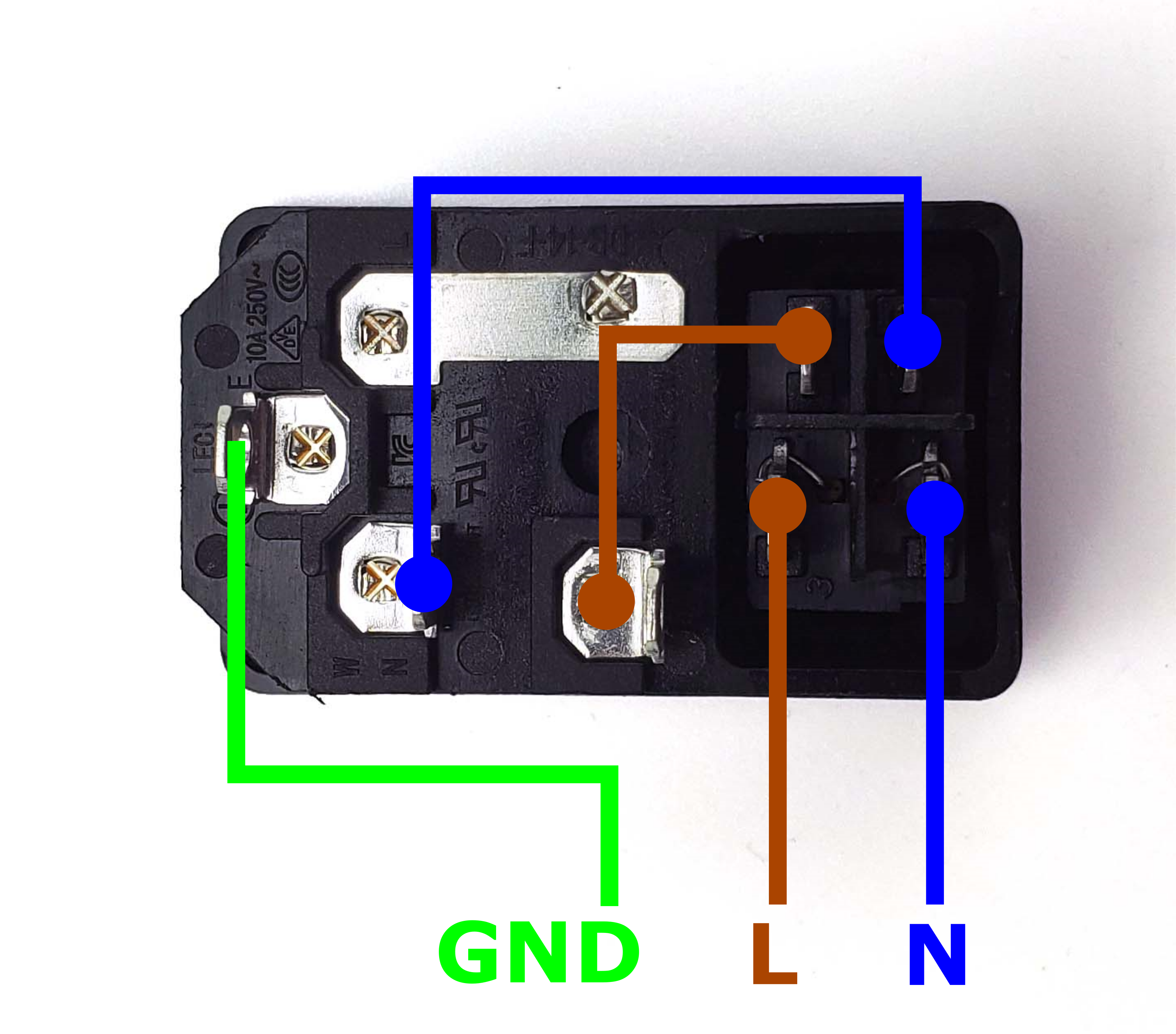
Take the inlet cable included in the kit and attach the wires using the above layout as reference. When wired correctly, your live wire will be protected by a fuse, and the switch on the front side of the inlet will operate correctly (lights up when turned on).
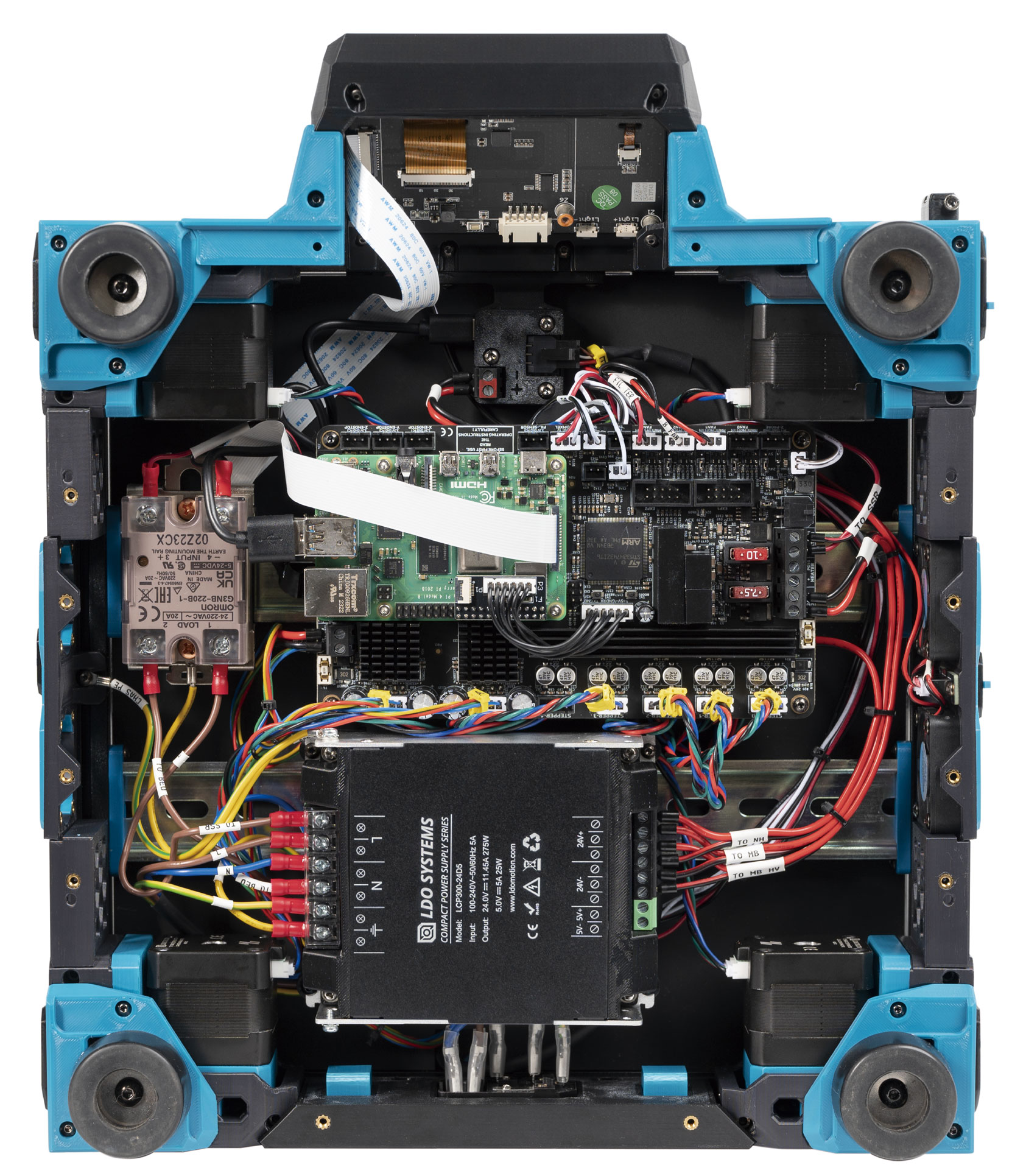
¶ Preparing the Mainboard (LDO Voron Leviathan Board)
Let's prepare our mainboard before proceeding with further wiring:
- We need a Leviathan Bracket Left and Leviathan Bracket Right and two Din Clips which can be downloaded here. These will allow your mainboard to be clipped onto DIN rails later.
- Refer to this guide LDO VORON Leviathan V1.3 to prepare your Leviathan Board.
¶ Installing the DIN Rails
These DIN rails run from left to right.
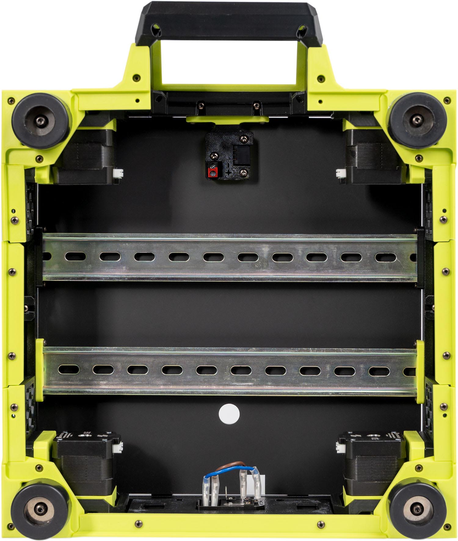
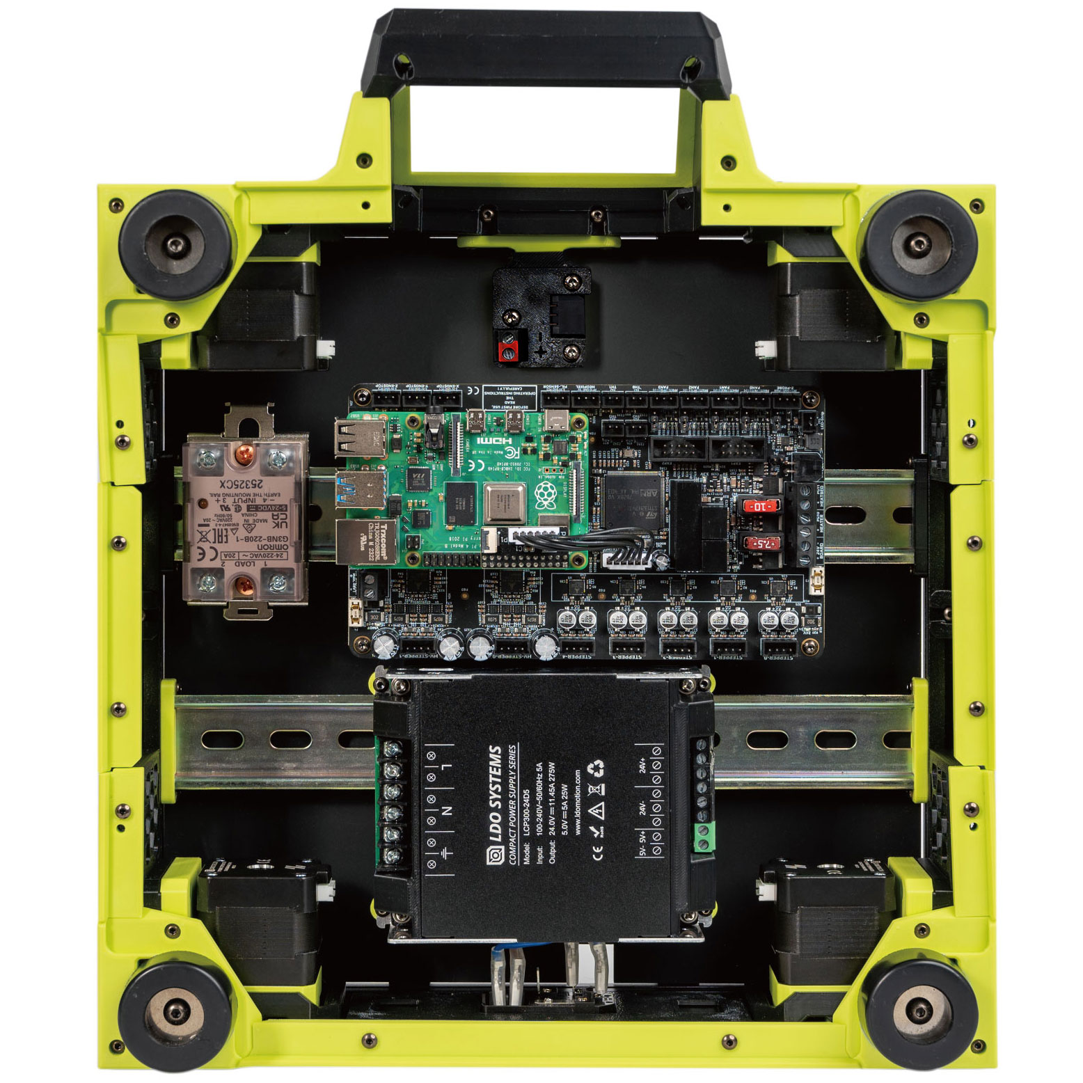
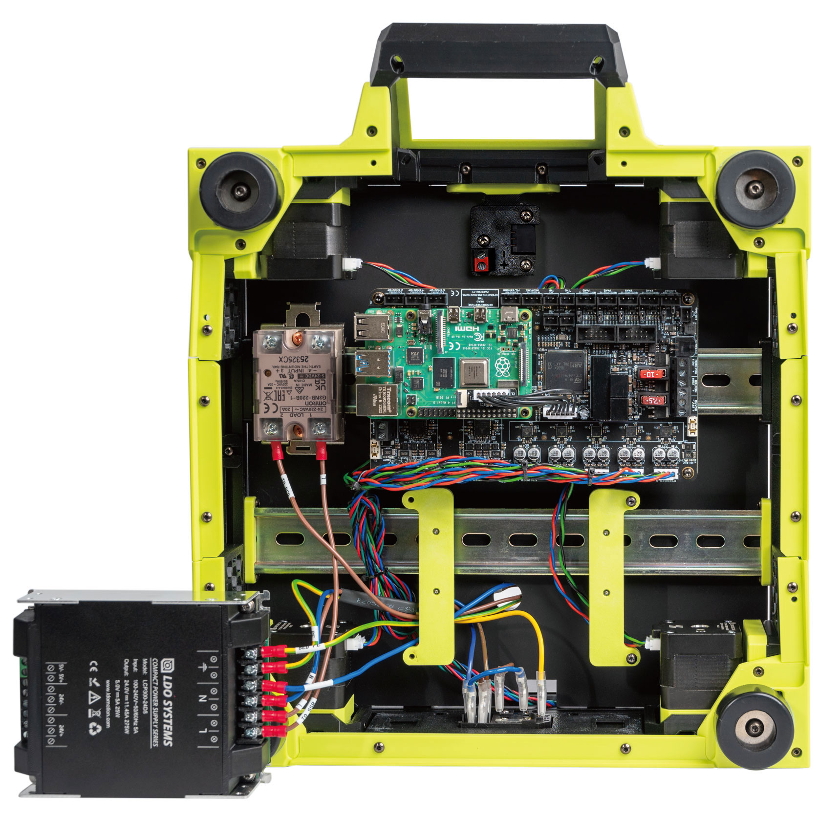
¶ General Placement
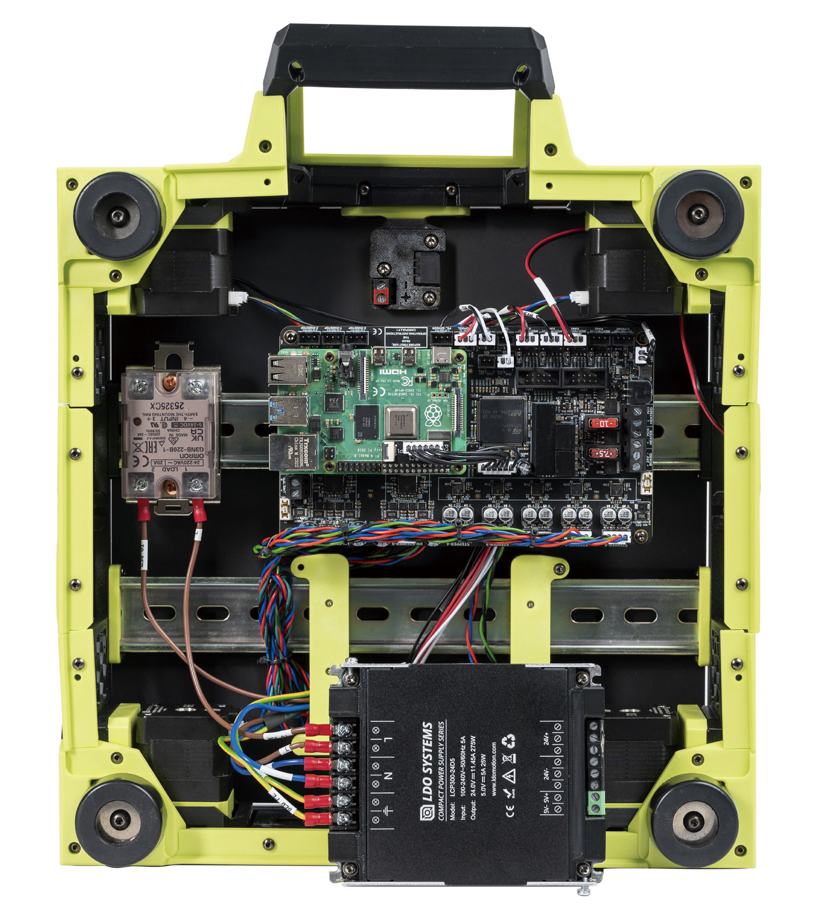
In this step, we will place the electronic components as shown in the picture below. The positioning of the components is not as critical, as they can be adjusted as needed later on.
For easier wiring, it’s recommended not to install the power supply yet — wait until all the wiring is completed before mounting it.
¶ Connecting Steppers
In this step, we will install all the stepper motor cables (except for the E motor). Follow the table and diagram below:
| Stepper Motor | Physical Position* | Controller Position |
| A | Rear Right of Gantry | HV-STEPPER-1 |
| B | Rear Left of Gantry | HV-STEPPER-0 |
| Z0 | Front Left | STEPPER-0 |
| Z1 | Rear Left | STEPPER-1 |
| Z2 | Rear Right | STEPPER-2 |
| Z3 | Front Right | STEPPER-3 |
| <NOT USED> | <NOT USED> | STEPPER-4 |
*All positions are specified as if standing in front of an upright printer and looking towards it.
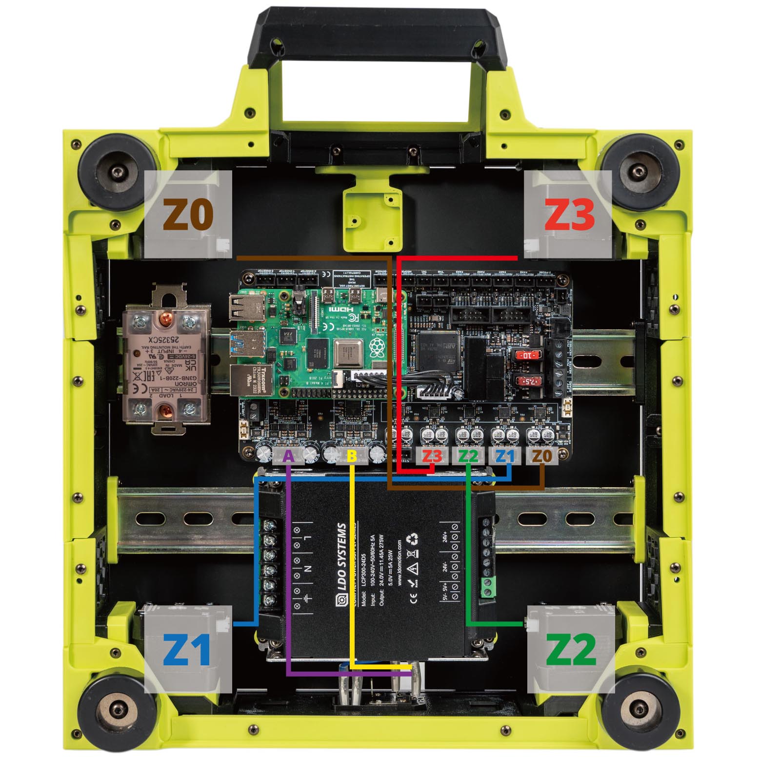
The end result should look like this:
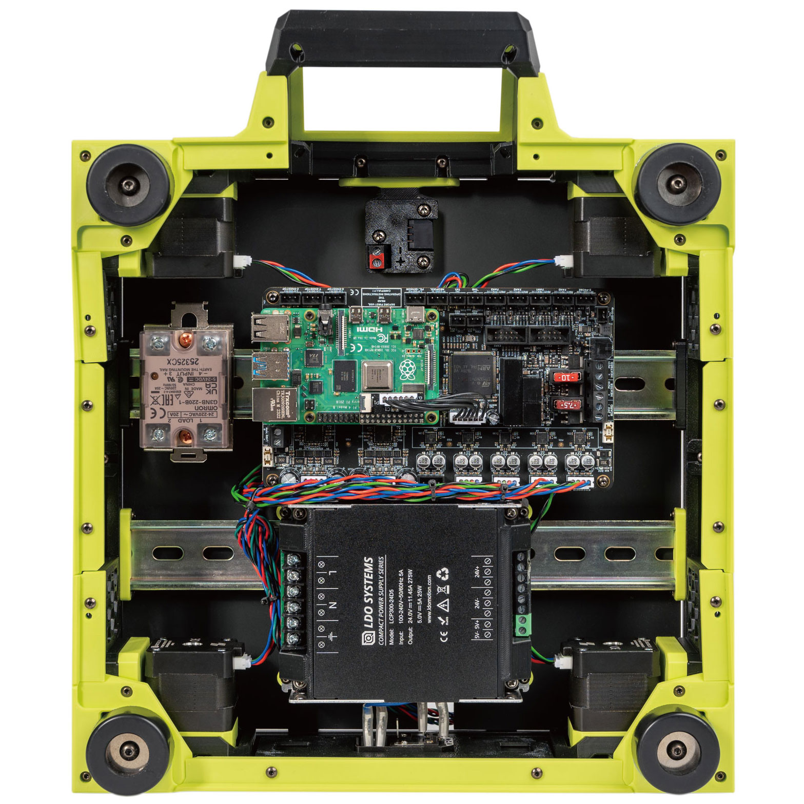
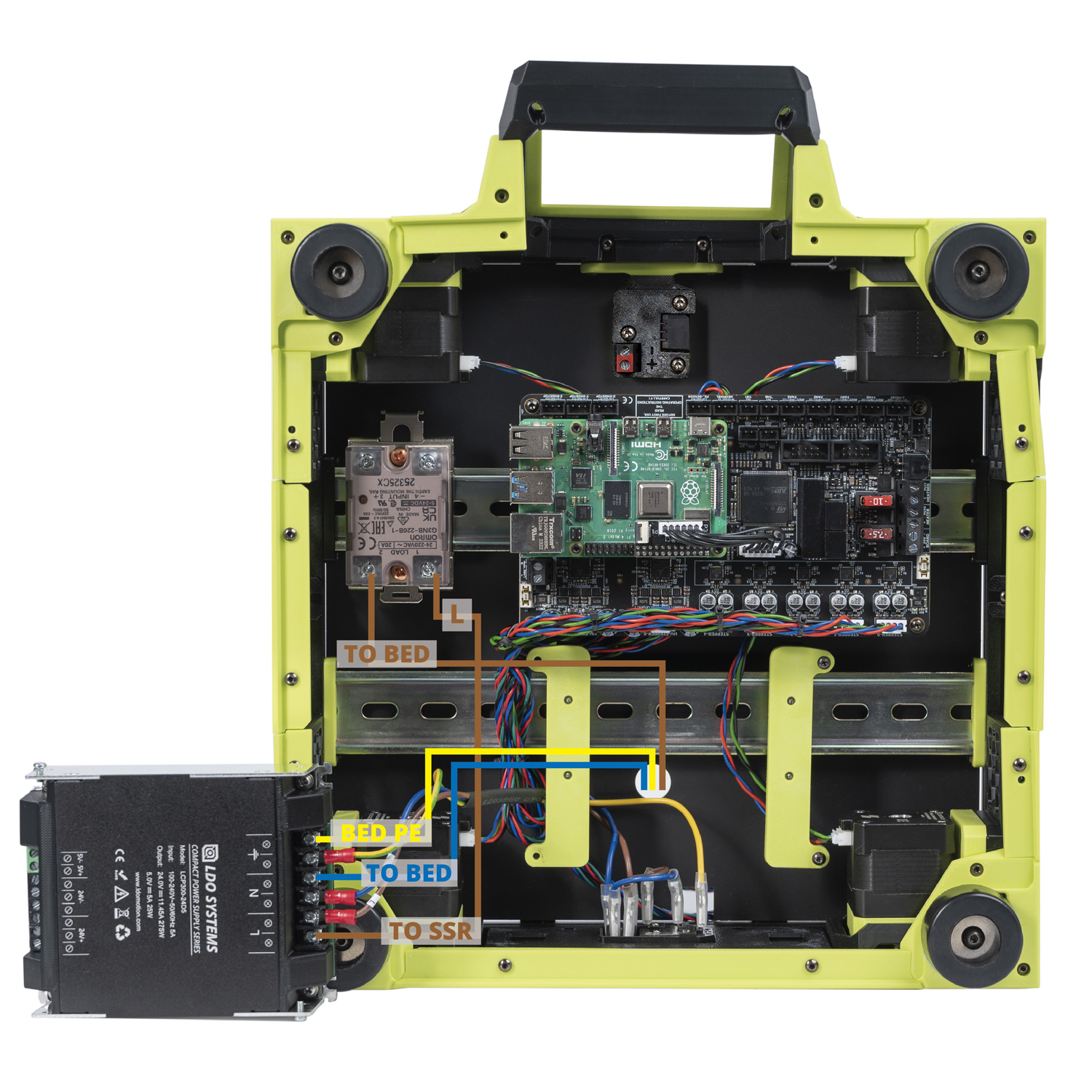
¶ Connecting Inlet and PSU
In this step we will connect the AC Inlet and the PSU. Follow the following diagram:
The end result should look like the following:
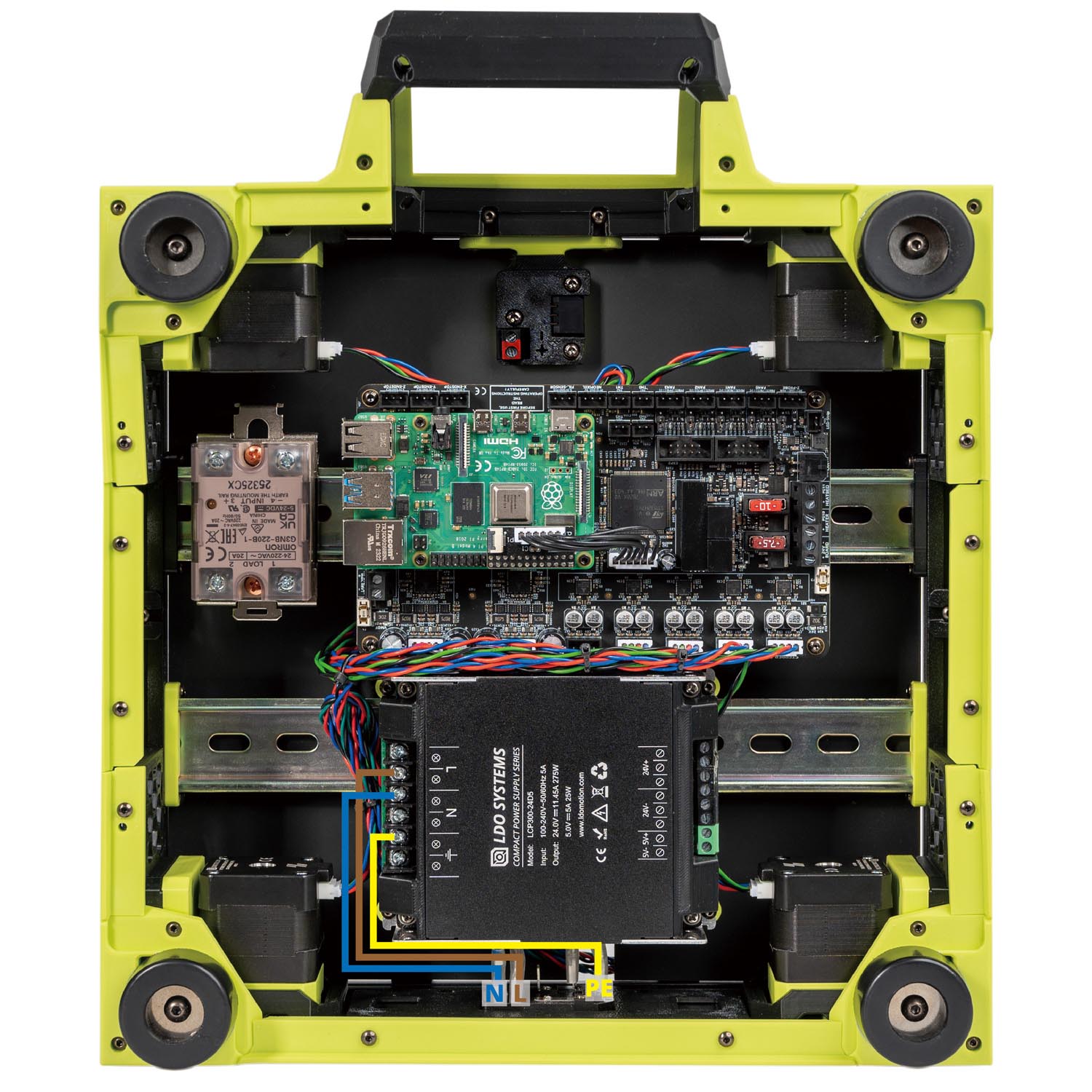
¶ Checkpoint #1
Before moving on to the next step, let us check all the wiring so far. Incorrect wiring of AC/mains can be dangerous - therefore, always double check your work, and then triple check it once more:
- Remember to check everything without the power cable plugged into the inlet!
- Check that the blue, brown and yellow wires should go into their respective terminals.
- Use a multimeter to check continuity between all nodes of the same colour - they should be shorted.
- Use the multimeter to check continuity between Live, Neutral, Earth - they should not be shorted with each other.
- After checking all of the above, plug in the power cable and switch on the inlet: The power supply should turn on and it's LED should light up.
- Switch off the inlet and remove the plug, we can now move on to the next step.
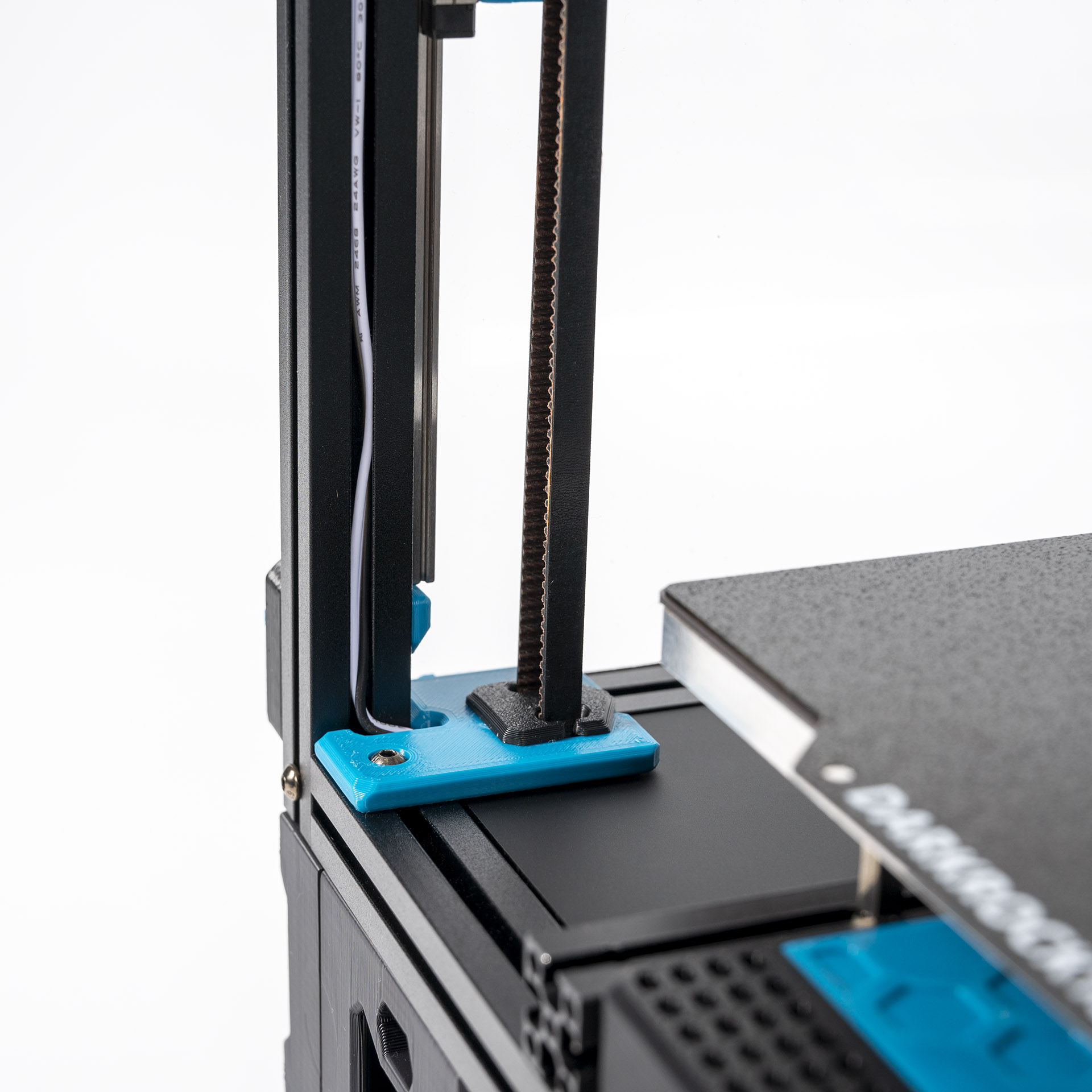
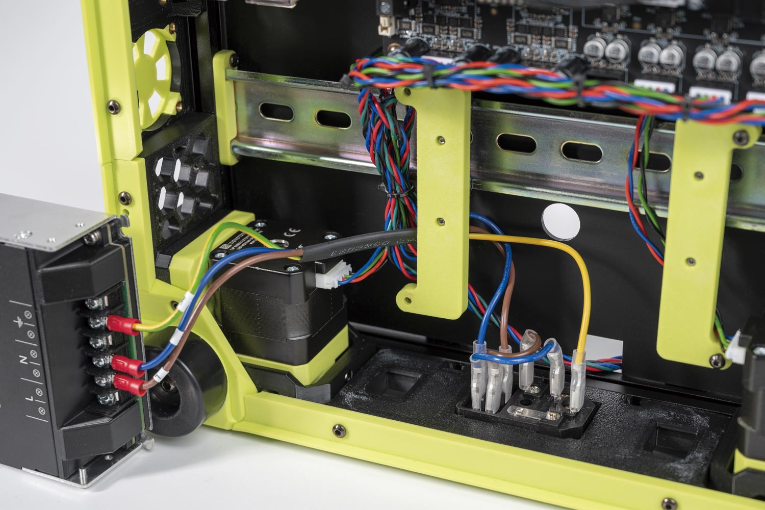
¶ Connecting Build Plate
In this step, we will make build plate connections.
- Connect the To Bed end of the heatpad to a PSU terminal.
- Connect the Bed PE end of the heatpad to a PSU terminal.
- Connect the To Bed end of the headpad to LOAD 2 on the SSR.
- Connect the L end of the cable to LOAD 1 on the SSR and the To SSR end to a PSU terminal .
The overall result:
¶ Connecting the Gantry Cables
In this step, we will connect the other ends of the Bed Aux Umbilical PCB cable, LED strip cable and PCB Fan to the Leviathan controller board.
- Connect the FILTER to the 3 pin connectors (Labelled FAN3) on the board.
- Connect the B FAN cable to the 3 pin connectors (Labelled FAN2) on the board.
- Connect the RGB to the 3 pin connector (Labelled NEOPIXEL) on the board.
- Connect the THB to the 3 pin connector (Labelled TH0) on the board.
- Connect the THP to the 3 pin connector (Labelled TH1) on the board.
- Connect the PCB FAN cable to the 3 pin connectors (Labelled FAN1) on the board.
- Connect the LED strip cable to the 2 pin connector (Labelled LED-Strip) on the board.
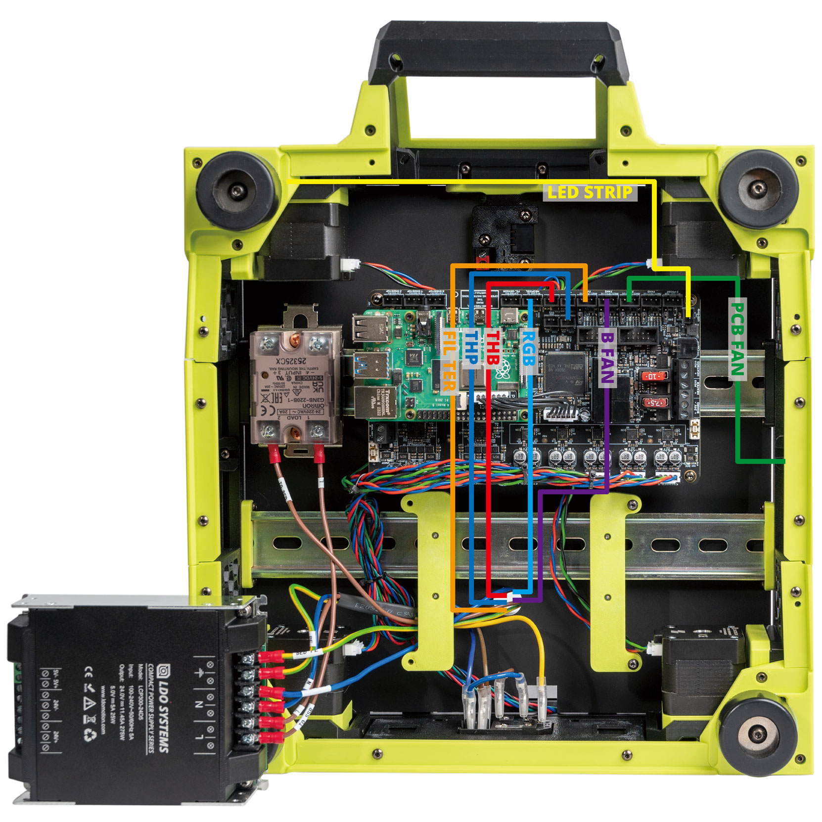
The overall result:
¶ Connecting the 24V
In this step, we will connect the power supply to the controller board and the relay.
- Connect the 24V end of the 24V to MB cable to the Board terminals on the controller and the TO MB end to the PSU.
- Connect the HV end of the HV to MB HV cable to the controller board and the TO MB HV end to the PSU.
- Connect the SSR SIG end of the SSR to MB cable to INPUT 3&4 on the SSR. The red cable goes to INPUT 3 and the black cable goes to INPUT 4. Connect the To SSR end to the HEATBED terminals on the controller.
- Pay attention to the polarities.
- The SSR connection is critical, an incorrect connection can cause catastrophic damage. Pay close attention to the numbers labelled on the SSR and position of the yellow LED light.
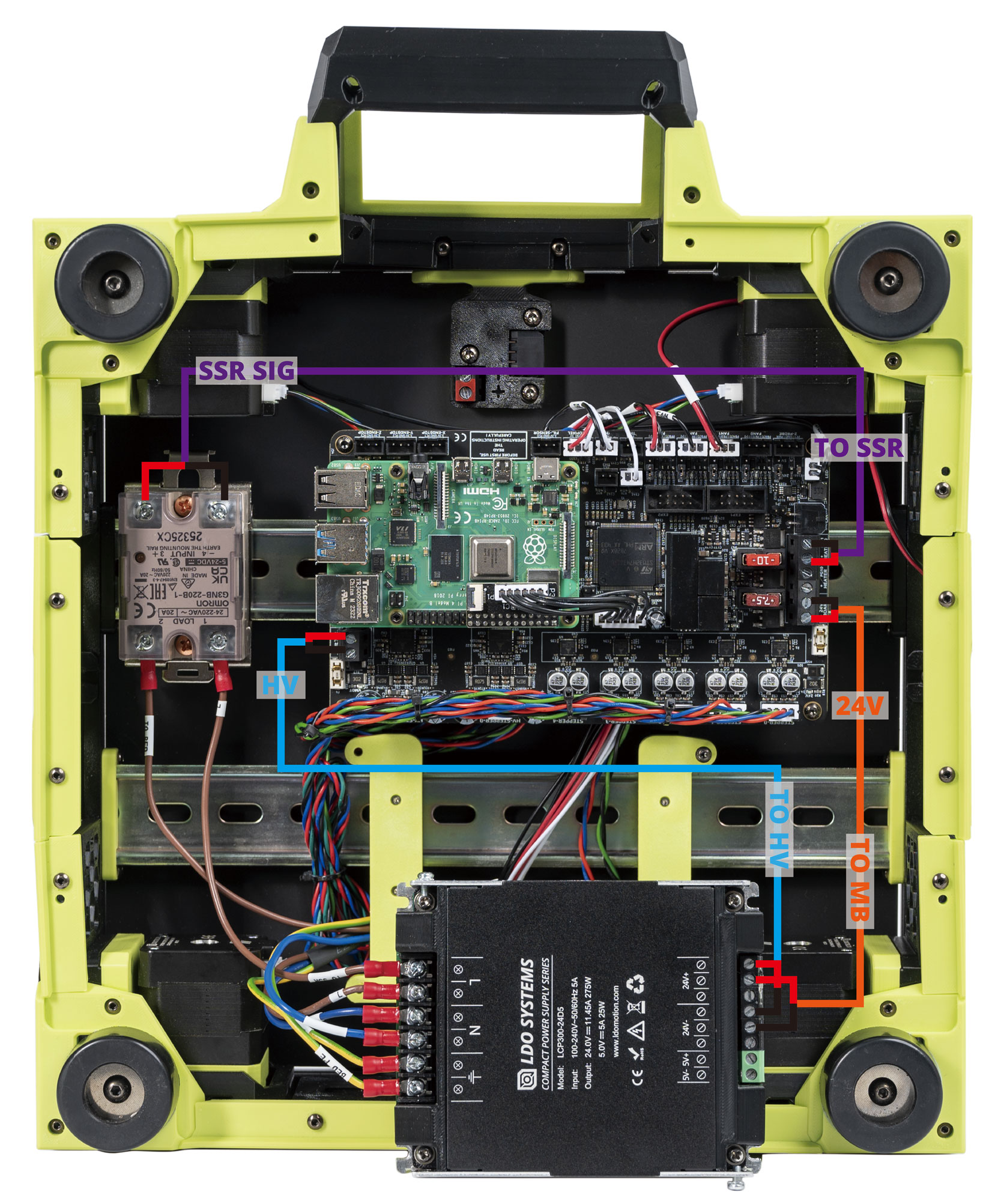
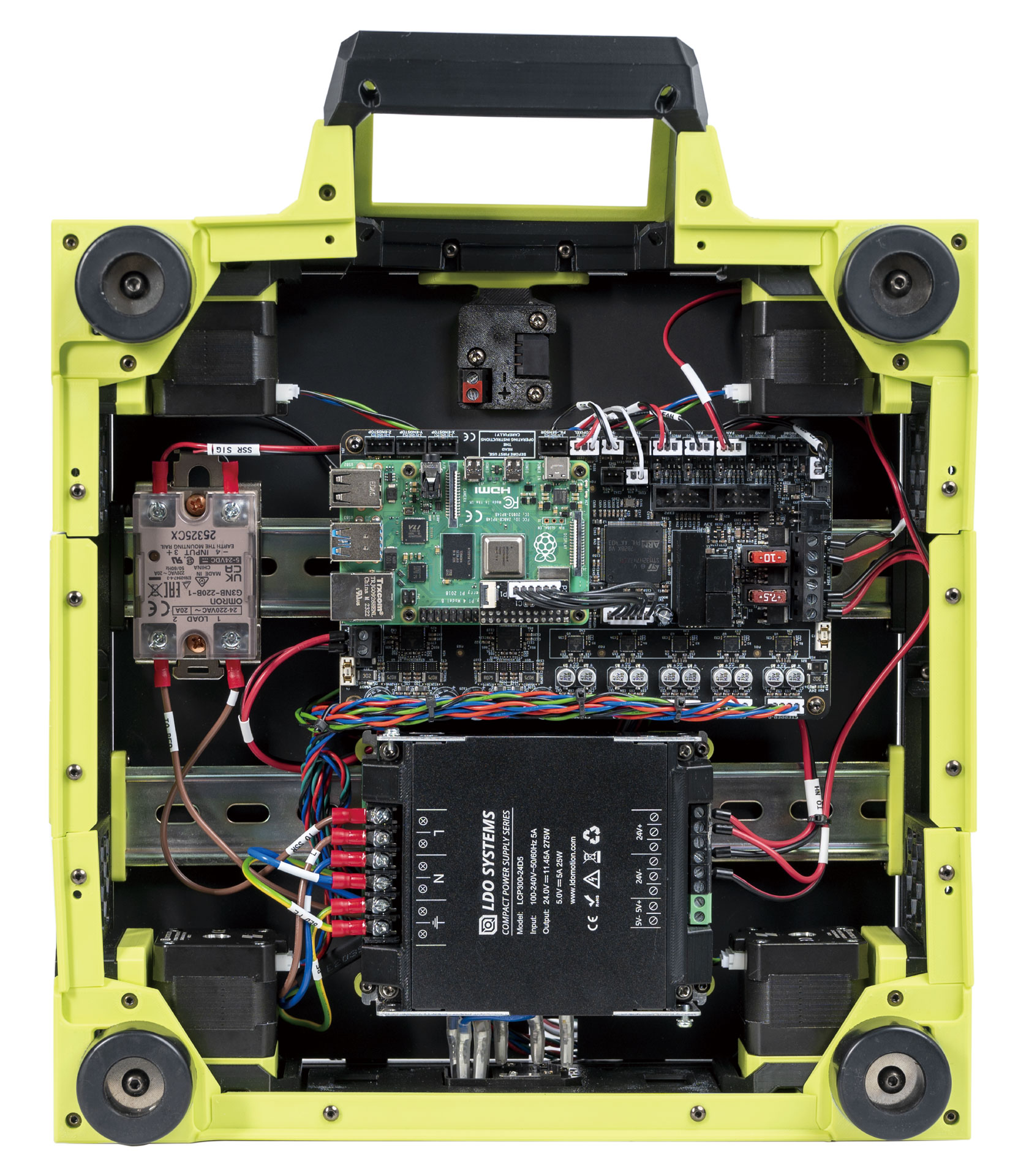
The result is below:
¶ Connecting the FFC Cable, USB Cable and Fame PE
In this step, we will connect the remanining items.
- Use the provided ribbon cable to connect the touch display to the Raspberry Pi. The ribbon cables need to be connected in a specific orientation - consult this guide (note the blue backing).
- Connect the USB cable to the Raspberry Pi and the USB Adapter PCB.
- Connect the 24V end of the 24V to NH cable to the USB Adapter PCB and the TO NH end to the PSU. Pay attention to the polarities.
- Connect the E motor cable to the USB Adapter PCB.
- Connect the CHAS PE end to the top-left screw of the power supply and tighten the screw. Connect the other end to the screw located in the middle of the left frame。
- Connect the SSR PE end to the top-left screw of the power supply and tighten the screw. Connect the other end to the bottom screw on the SSR.
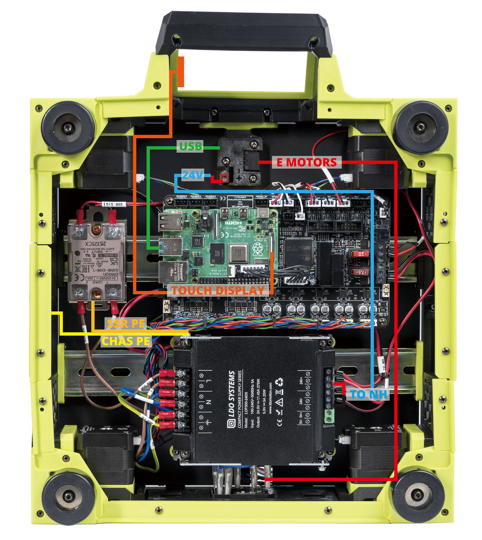
Here is the result:
¶ Finish Line
Congratulations! You have completed all the wiring! All that is left now is to put the PSU back to the bracket!
¶ Software Setup
Now that you have completed hardware wiring, it is time to move on to software setup. The following sections outline resources you can use to finish setting up software for your printer.
¶ Raspberry Pi OS Setup
We first need to install an operating system onto your Raspberry Pi. The easiest way to do this is to use their official imager.
- Download and run the Raspberry Pi Imager.
- Under Advanced options, enable SSH, set a username and password, and enter your WIFI info.
- Under Operating System Choose Raspberry Pi OS (other) -> Raspberry Pi OS Lite (32bit).
- Insert the SD card provided in the kit and choose it under storage. Click Write and wait for the Imager to finish writing the data into the SD card.
- Remove the SD card from your computer and insert it into the Raspberry Pi
¶ Remotely Accessing Your Raspberry Pi via SSH
Many of the following steps below require you to remotely run commands on your Raspberry Pi via SSH. If you are on Windows, putty is the goto tool. If you are on Mac OS, you can simply run ssh on your Terminal. For more info about remotely accessing your Raspberry Pi using SSH, read this article.
¶ Klipper and Web Interface Setup
On your Raspberry Pi, you will need to install Raspberry Pi OS Lite, Klipper, and a web interface to manage your printer. The most popular options for a web interface are Fluidd and Mainsail - both are great options with similar controls, you can't go wrong picking either of them. To make installation a breeze, we recommend using KIAUH, which is a script that helps you install Klipper, Fluidd/Mainsail and any other dependancies that may be required.
- Follow the instructions on the KIAUH github page.
- Use KIAUH to install Klipper, then Moonraker, then Fluidd or Mainsail, then KlipperScreen.
¶ Setting up the Touch Screen
If you followed the previous step with KIAUH, then KlipperScreen should be successfully installed. Read this guide for information on touchscreen setup and instructions for rotating screen orientation.
¶ Mainboard Firmware Setup
The Leviathan board is pre-programmed when you receive it.
If you need to update Klipper firmware, follow the instructions on the this site to install Klipper Firmware to the Leviathan board.
¶ Determining the USB ID of your Mainboard and Toolboards
In this step we will obtain the USB ID of the Leviathan mainboard and Nitehawk toolboard. You will need these IDs in the next step when modifying your printer.cfg. Refer to this guide for different methods of obtaining the USB ID.
Since our printer consists of two boards (Leviathan mainboard and Nitehawk), we will need to correctly match up the USB ID of each board.
- The Nitehawk uses an RP2040 MCU, therefore its ID will be in a format similar to
usb-Klipper_rp2040_0123456789ABCDEF-if00. - The Leviathan uses an STM32F446 MCU, therefore its ID will be in a format similar to
usb-Klipper_stmf743xx_0123456789ABCDEF-if00.
¶ Klipper Configuration
With software and firmware both successfully installed. We can now move on to adding Klipper configuration files. These configuration files basically tell Klipper how our printer is wired. It also contains other useful data such as custom macros, tuning values, and so on.
- Open your printer's web interface by entering your Raspberry Pi's IP address in any browser. Initially, you will see an error message indicating a missing “printer.cfg” file.
- Download the configuration file here and upload it via the Mainsail/Fluidd web interface. In Mainsail, go to Machine (Wrench icon). In Fluidd, goto Configuration ( {…} icon ). Both web interfaces allow you to upload by directly drag and drop the files onto the their webpage.
- Edit the printer.cfg file, under the
[mcu]section, replace{REPLACE WITH YOUR SERIAL}with the Leviathan MCU path you obtained in the previous steps. Please check next section on how to find your serial ID.
¶ Initial Printer Setup and Tuning
With all the configuration files in place, you should now be able to use Fluidd/Mainsail to perform basic controls on your 3D printer. However, there are still a few more stepss you should follow before starting your first print. Refer to the Voron V2.4 initial startup guide on the Voron documentation site.