¶ Introduction
Nitehawk-SB v2 by LDO is a toolboard specifically designed for the Voron Stealthburner toolhead. It is a toolhead PCB featuring STM32G0B1 MCU, TMC2209 stepper drive, ADXL345 accelerometer, USB HUB all integrated into one board. Nitehawk v2 retains the same form factor of the original Nitehawk-SB but much of the circuitry and layout has been completely redesigned from the ground up.
Nitehawk uses USB communication with the RPI rather than CAN. So the software and hardware setup is far simpler and familiar to most people who have setup Klipper printers before.
¶ Features
- Convenient wiring, no more complicated and error prone breakout cables - nitehawk only requires 24V power and a USB connector to the RPI host.
- USB Klipper connection, no additional software or hardware setup compared to CAN.
- Custom toolhead cable, a single combined USB data and power cable rated for drag chain use, but can also be used in umbilical configuration.
- Convenient Input Shaping, run input shaper calibration at anytime with an onboard accelerometer.
- Tacho enabled fans, both hotend and part fan ports are three pin tachometer compatible, allowing for additional diagnostics and safety.
- Secondary USB port, an onboard USB port allows you to connect a second USB device to your toolhead without running an additional umbilical cable.
¶ Changes from the Nitehawk-SB v1
- Onboard microcontroller changed from RP2040 to STM32G0B1.
- Added USB hub and secondary USB port as in Nitehawk-36.
- Added general purpose I2C port.
- Reversed connector gender between main toolboard and fan adapter PCB. The headers are also now keyed prevent misalignment.
- Probe, TH0, XY Endstop ports changed from JST-XH2.5 to JST-PH2.0.
- Vastly Improved ESD performance.
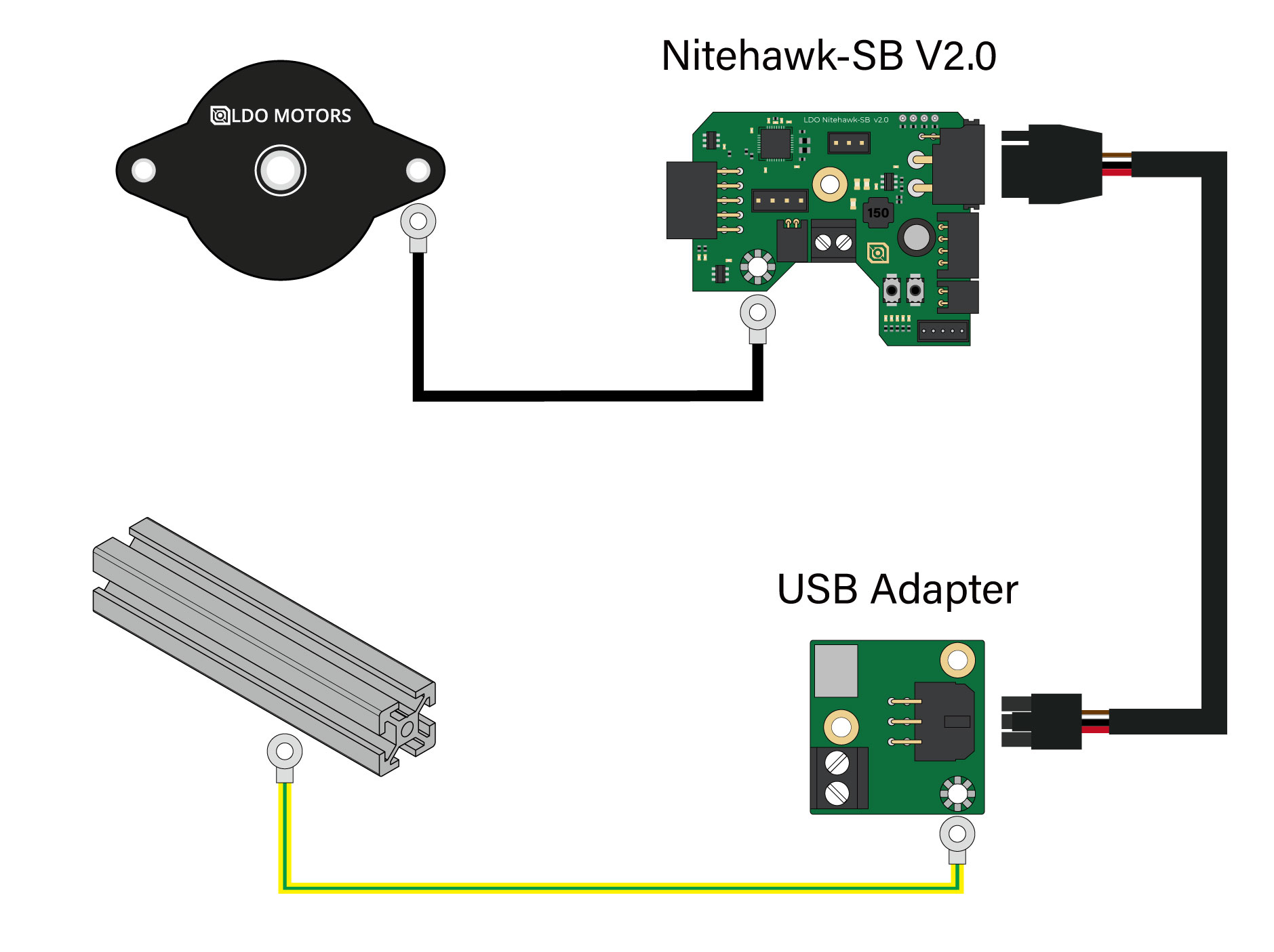
¶ System Overview
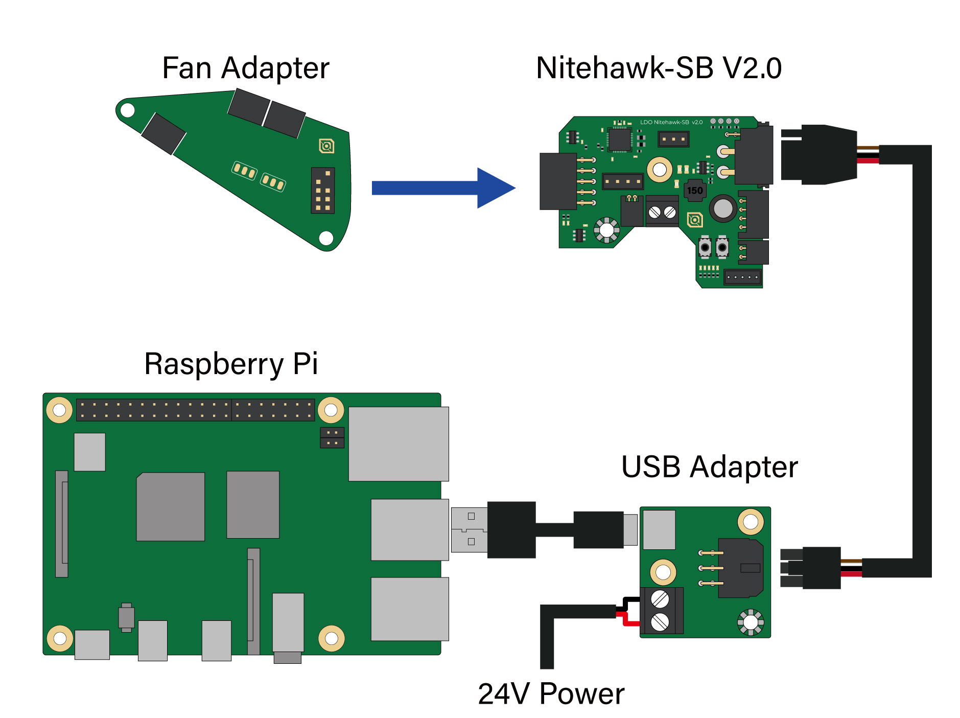
The Nitehawk system consists of three PCBs and the Umbilical Cable. A simplified wiring diagram is shown below:
- Nitehawk-SB v2, this is the main PCB, which houses the MCU, stepper driver, fan drivers, and other circuits.
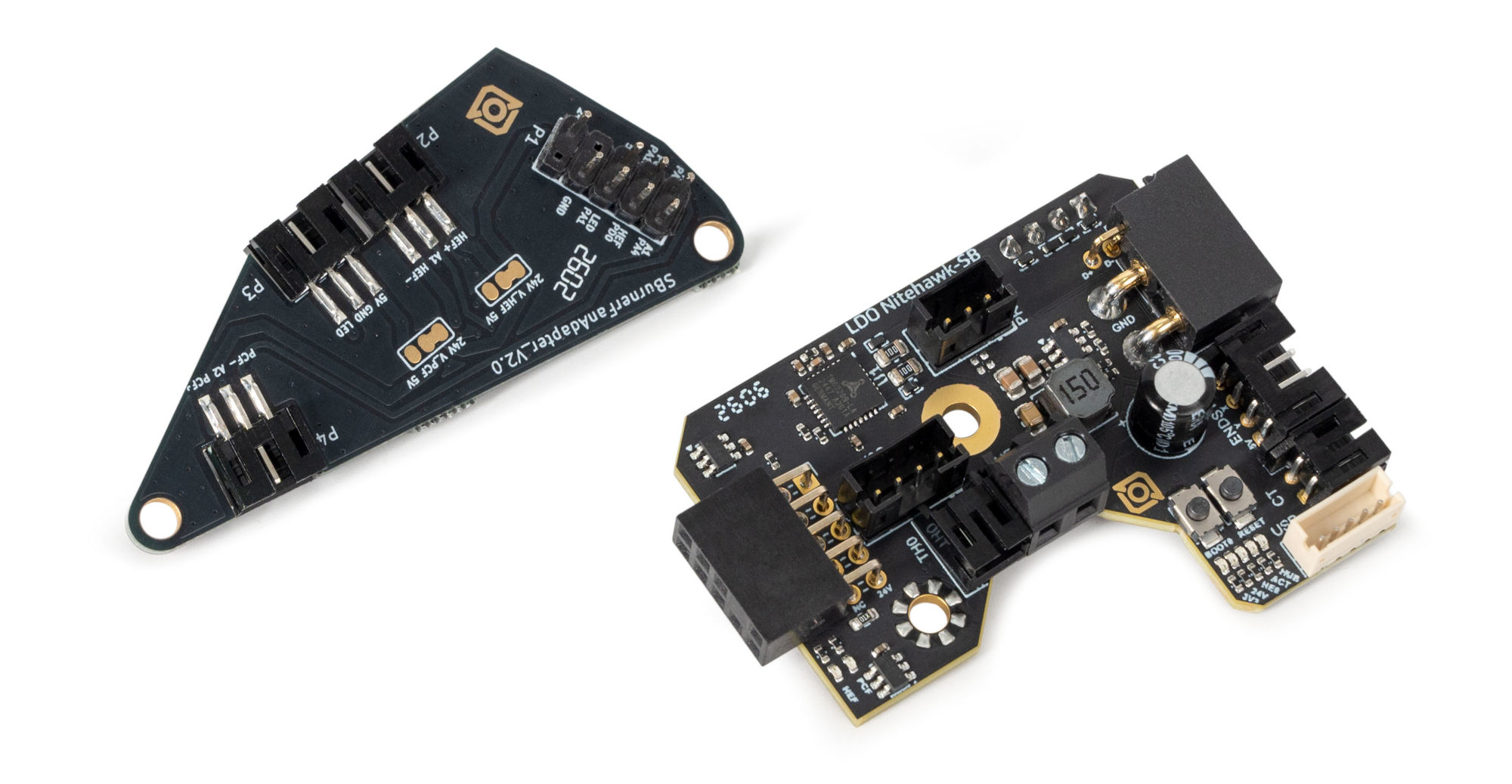
- Fan Adapter, this is simple PCB receives the part fan, hotend fan, and neopixels and connects them to the main Nitehawk PCB via headers. The main purpose of this seperation is to allow the Stealthburner front to be easily detactable for maintenance.
- Umbilical Cable, this is a custom flex cable that is rated for drag chain use. It delivers 24V power to the main Nitehawk PCB while also carrying USB data.
- USB Adapter, this simple PCB combines 24V power from the power supply and USB data from the Raspberry Pi into a unified connection to the main Nitehawk PCB via the Umbilical cable.
¶ Printed Parts
Nitehawk-SB works with a standard Stealthburner toolhead, and is compatible with both Clockwork 2 and Galileo 2. However there are a few additional custom printed parts. The printed parts are available in the Nitehawk github repo https://github.com/MotorDynamicsLab/Nitehawk-SB
- USB Adapter Mount, this is the mount for the USB adapter PCB. It is designed to be used with a standard Voron DIN clip and can be mounted in two different orientations. A newly designed cover exposes one of the mounting points to connect a grounding point.
- Cable Door, this part has been slightly modified from Hartk’s original, with a zip tie anchor added for the external chamber thermistor. The door also accepts a Mx3 Captive screw so it doesn’t get lost easily when you open the door.
- Chain Anchor Tilted, This is tilts the drag chain ever so slightly to help it clear the left XY joint and also avoid rubbing the CT connector on the toolboard.
¶ Klipper Config Files
A Klipper Configuation can be found in the Nitehawk-SBv2 github repo here.
¶ Port and Pin Definitions
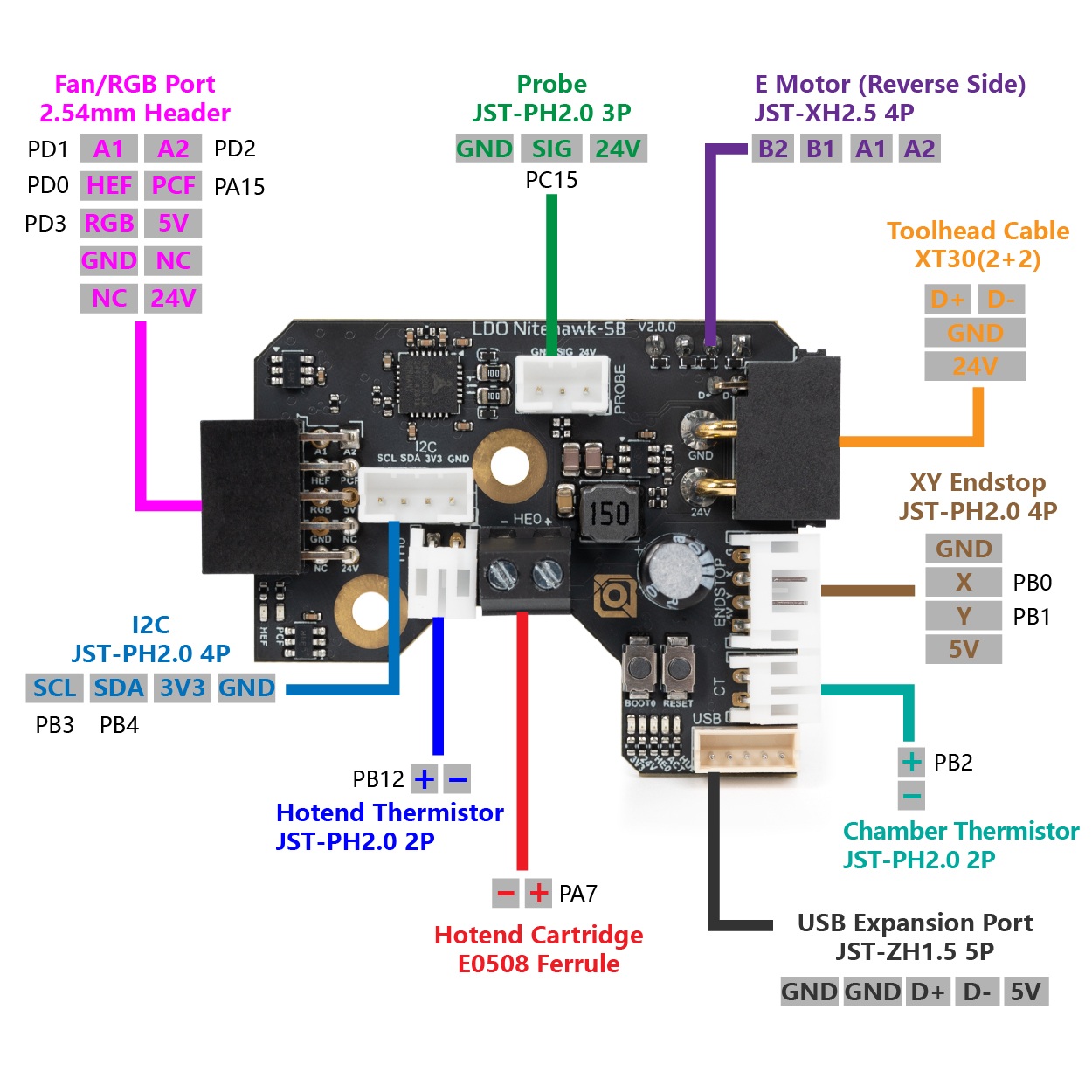
| Device/Port | PCB Label | Connector Type | MCU Pin | Description |
| X/Y Endstop | Endstop | JST-PH 4P | PB0/PB1 (X/Y) | Connects to the X and Y endstop. X endstop is PB0 and Y endstop is PB1. |
| Hotend Heater | HE0 | Screw Terminal / E0508 | PA7 | Connects to the hotend heater. |
| Hotend Thermistor | TH0 | JST-PH 2P | PB12 | Connects to the hotend thermistor. Uses a 2.2kΩ pull up resistor. |
| Part Cooling Fan | PCF (Fan adapter PCB) | 2.54mm Header | PA15/PD2 (fan/tacho) | Connects to part cooling fan (via the fan adapter PCB). The fan control pin is PA15 and the tachometer sensor pin is PD2. |
| Hotend Fan | HEF (Fan adapter PCB) | 2.54mm Header | PD0/PD1 (fan/tacho) | Connects to hotend fan (via the fan adapter PCB). The fan control pin is PD0 and the tachometer sensor pin is PD1. |
| Chamber Thermistor | CT | JST-PH 2P | PB2 | Chamber Thermistor port. Connects to an external thermistor. Uses a 4.7kΩ pull up resistor. |
| Probe | PROBE | JST-PH 3P | PC15 | Probe for bed leveling and/or Z sensing. 24V power only. |
| USB Expansion Port | JST-ZH1.5 5P | Allows connection to a secondary USB device. | ||
| I2C | I2C | JST-PH 4P | PB3/PB4 (scl/sda) | Allows connection to a secondary I2C device. |
| Motor | MOTOR | JST-XH 4P | PB8/PB9/PC14/PB7/PB6 (step/dir/ena/uart/tx) | A stepper motor port for the extruder. Driven by a TMC2209 chip. The current sense resistor is 100 mΩ. Enable is active low |
| Neopixel | LED (Fan adapter PCB) | 2.54mm Header | PD3 | Connects to neopixel LEDs (via the fan adapter PCB). |
| Activity LED | ACT | N/A | PC6 | A small software controlled onboard LED. Active low. |
| Accelerometer | N/A | N/A | PB10/PA5/PA2/PA6 (cs/clk/mosi/miso) | ADXL345 accelerometer for input shaping. Controlled via software SPI. |
¶ Pinout: Fan Adapter PCB
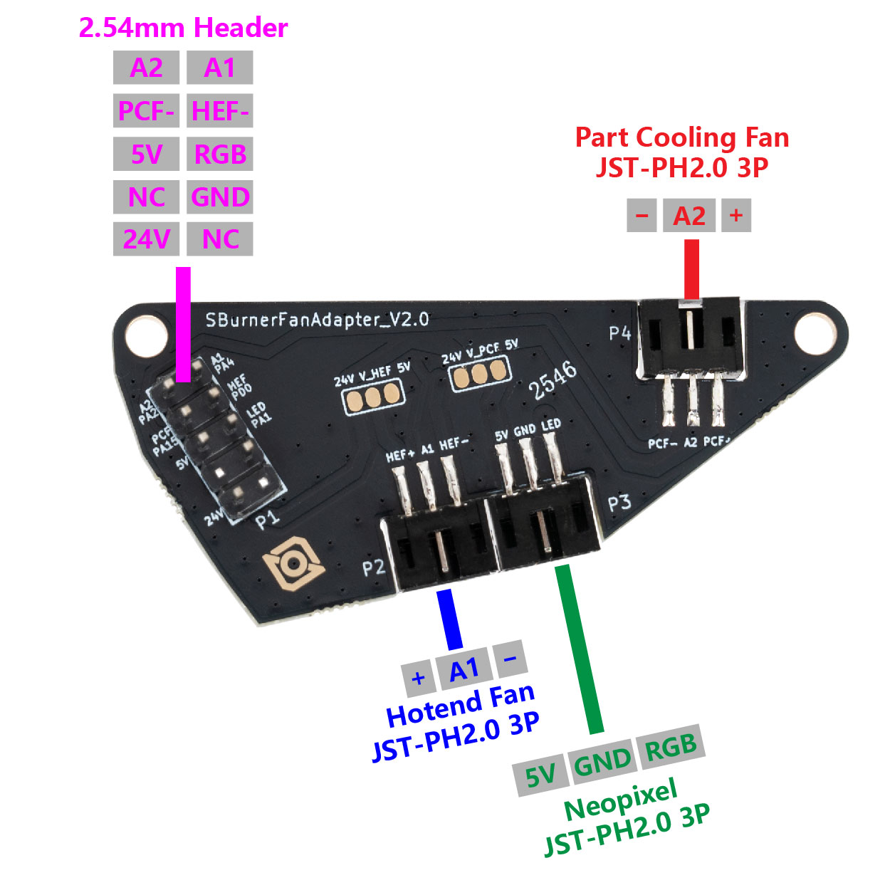
The table below briefly describes the purpose of each port located on the toolhead PCB.
| PCB Label | Name | Connector | Description |
| HEF+/A1/HEF- | Hotend Fan* | JST-PH-3P | Fan port for cooling the hotend heatsink. 24V/5V selectable, defaults to 24V. |
| PCF+/A2/PCF- | Part Cooling Fan* | JST-PH-3P | Port for part cooling fan. 24V/5V selectable, defaults to 24V. |
| 5V/GND/LED | Neopixel | JST-PH-3P | For connecting to the neopixel chain on the stealthburner. |
| Toolhead Cable | 2x10 M-Header | Plugs into the female header on the main toolhead PCB |
*If the rated current of your stepper motor is 1A, we recommend setting it below 0.7A. If you need more than 0.7A, please add extra heat dissipation for your board.
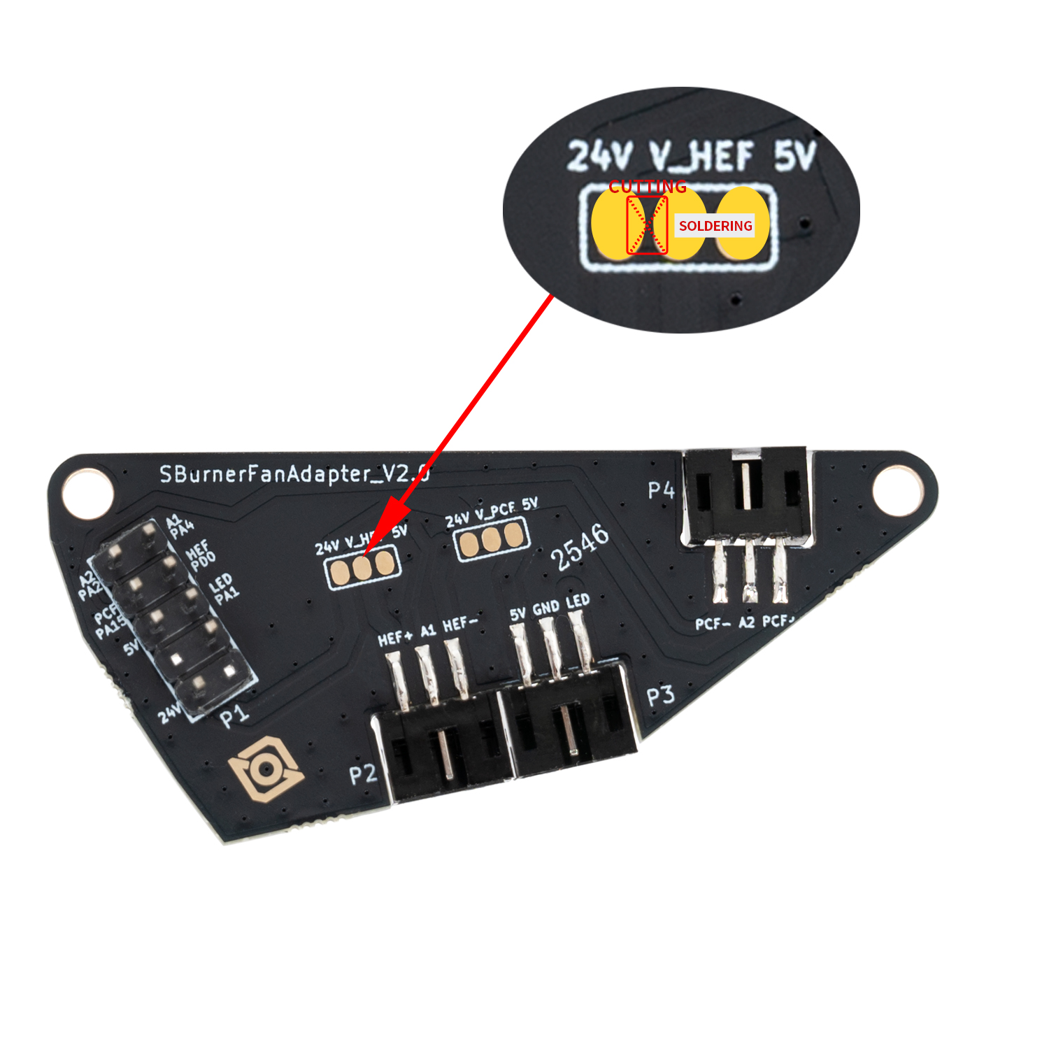
*The hotend fan and part fan can be independently changed to 5V in two steps:
- Severe the 24V connection by cutting the trace between the 24V pad and V_HEF/V_PCF pad
- Make a soldered bridge connection between the 5V pad and V_HEF/V_PCF pad
*When selecting 5V power supply, refer to the diagram:
Cut the trace between 24V and HEF. Solder a bridge between HEF and 5V. (Same applies to PCF operation.)
¶ Umbilical Cable
The umbilical cable connects the toolboard to the host (Raspberry Pi) via the USB adapter PCB. The cable combines layers of highly flexible insulation with anti-chafing sheathing and is specifically designed to carry USB data within the hostile environment of a cable chain, but can also be used in a traditional umbilical configuration. Its nominal bend radius is 28 mm and its maximum operating temperature is 105 °C.
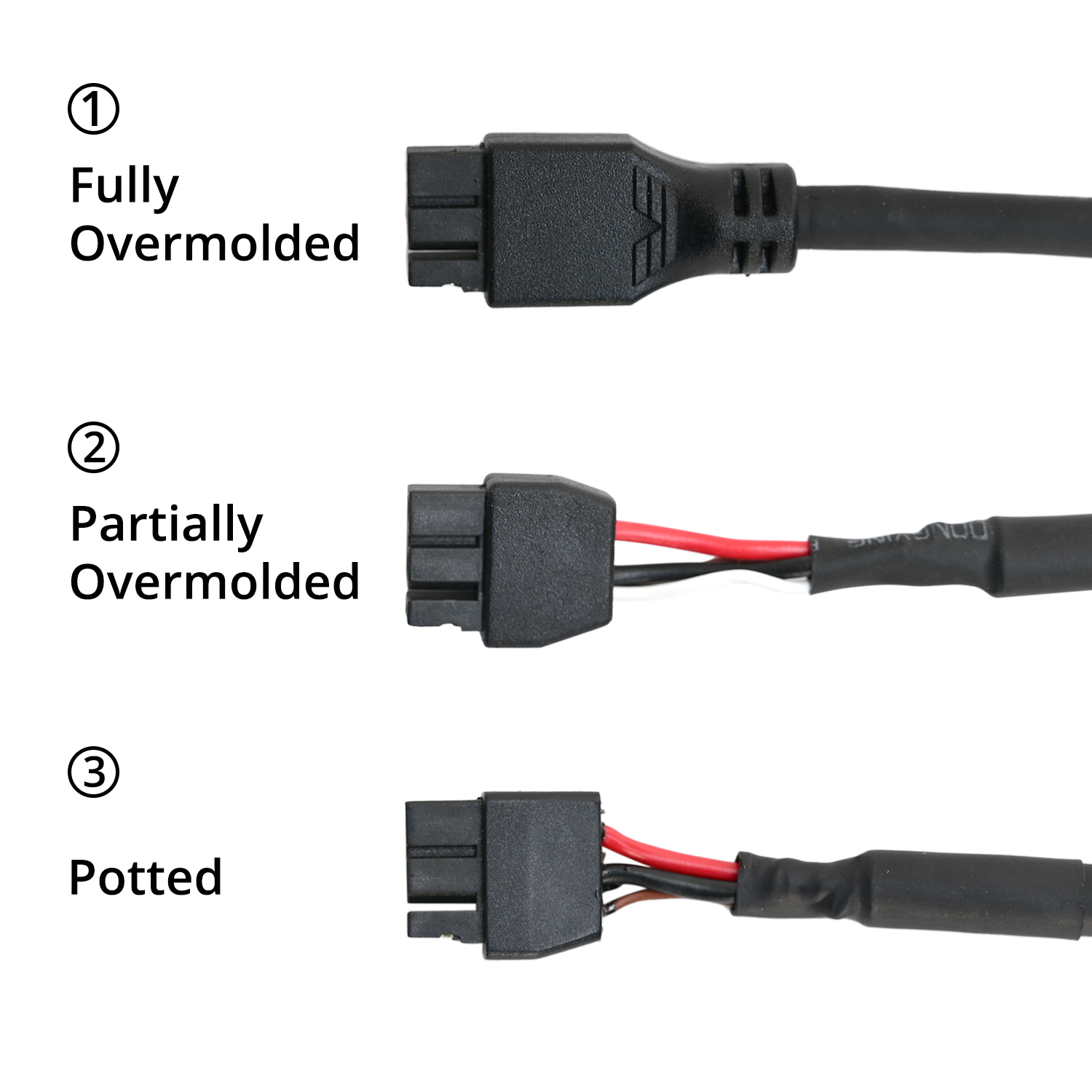
¶ Connector Variants (Toolboard side)
The connector used at the toolboard side is Amass XT30(2+2)-F. You may encounter three variants. all variants are compatible with Nitehawk-36, Nitehawk-SB, and Orbitool Toolboards but have different form factors,
- Partially Overmolded, this is the default version that is shipped with Nitehawk-SB and Voron kits. This version has a length of exposed wiring which allows the cable to bend easily at the toolboard side (needed when using Stealthburner + cable chains)
- Fully Overmolded, this is the default version shipped with the Nitehawk-36 KIT Rev C and later. It offers good strain relief but does not have the same flexibility at the connector end as variants #2 or #3.
- Note: This version is NOT included in the recall since it would have further delayed the replacement of the defective boards. We apologize for any confusion. We are working to produce more and will offer them at cost to existing customers once they become available.
- Potted, this variant shipped with the old Nitehawk-36 V1.2 and Nitehawk-SB kits. This variant is now deprecated and has been superceded by variant #1 and #2.
¶ Cable Pinout (Toolboard Side)
The following shows the detailed pinout of the XT30 connector:
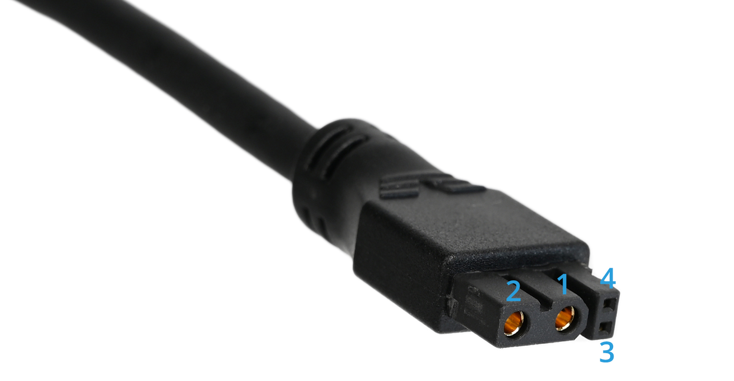
| Pin # | Name | Colour | Description |
| 1 | GND/Shielding | Black | Cable shielding and GND on the PCB share this pin. |
| 2 | 24V | Red | Provides 24V power to the toolboard. |
| 3 | D+ | Brown/Green | USB Data +. This conductor may be brown or green depending on batch. |
| 4 | D- | White | USB Data - |
¶ Cable Pinout (Adapter Side)
Micro-Fit 3.0 is the connector used at the USB adapter side of the umbilical cable. This connector is fairly easy to crimp and allows for the cable to be easily shortened if needed. Never plug or unplug this connector when the machine is powered! Doing so may risk damage to the Nitehawk or your Host (Raspberry Pi). The following shows the detailed pinout of the connector:
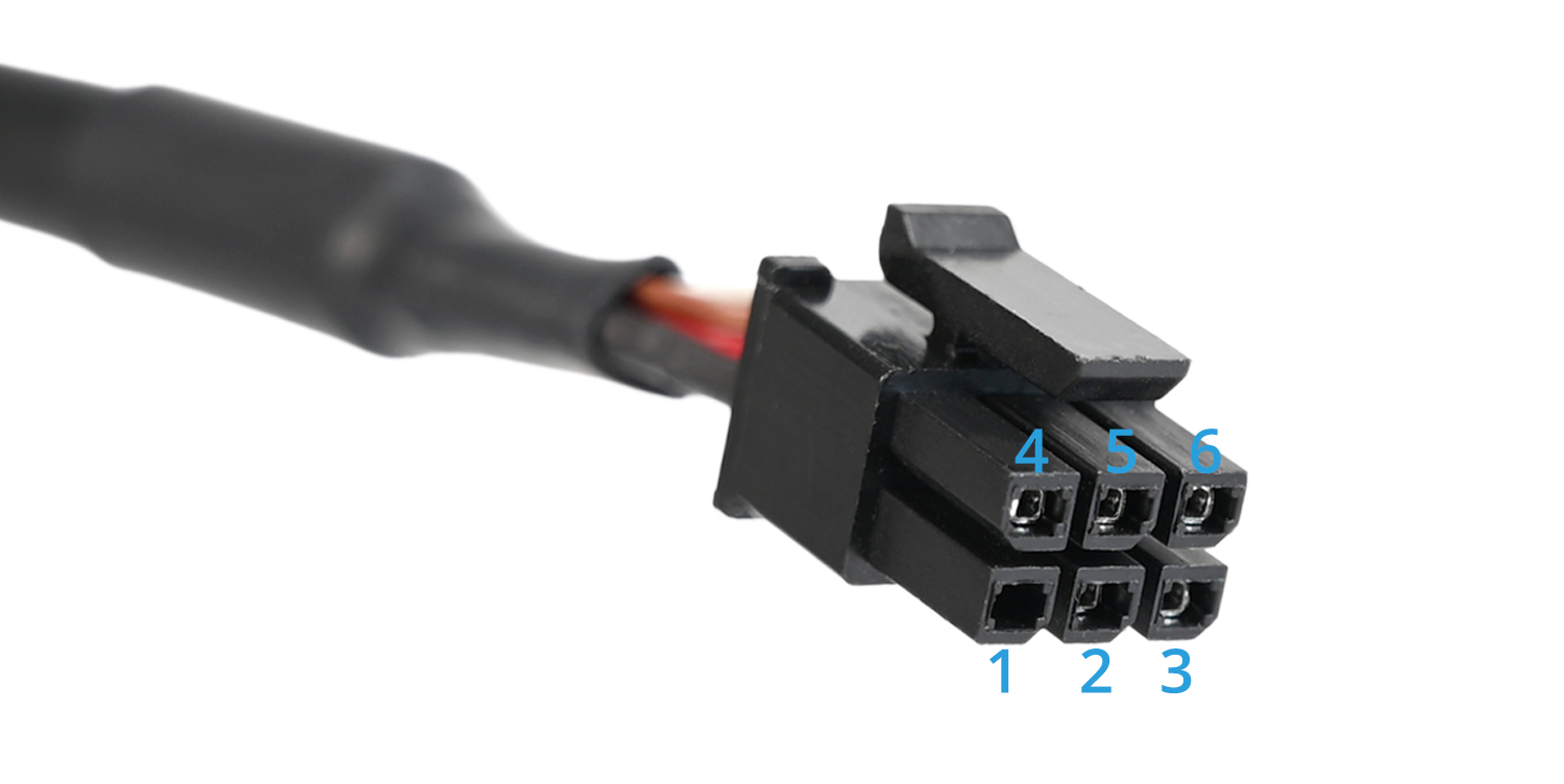
| Pin # | Name | Colour | Description |
| 1 | NC/GND | This pin is not connected at the cable, but is connected to GND on the PCB. | |
| 2 | NC/GND | This pin is not connected at the cable, but is connected to GND on the PCB. | |
| 3 | GND + Shielding | Black | GND and shielding share the same conductor. |
| 4 | D+ | Brown/Green | USB Data +. This conductor may be brown or green depending on batch. |
| 5 | D- | White | USB Data - |
| 6 | 24V | Red | Provides 24V power to the toolboard. |
¶ Electrical Specifications
| Parameter | Symbol | Minimum | Typical | Maximum | Unit | Comments |
| Power Supply Input | Vin | 20 | 24 | 28 | V | power input for the toolboard |
| 5V Current | Irpi | 5 | A | current output for the 5V buck converter | ||
| Fan Current(HEF, PCF) | Ifan | 1 | A | current rating for each fan port (HEF and PCF). | ||
| Hotend Current | Ihe | 4.5 | A | limited by max. continuous current of mosfet |
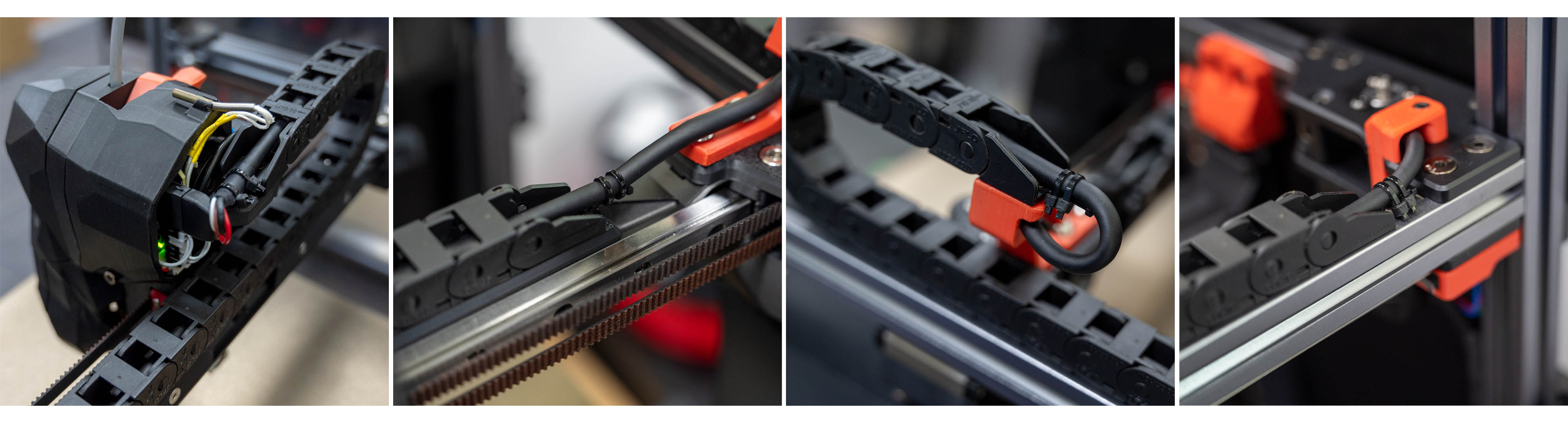
¶ Working with Cable Chains
When installing the umbilical cable through cable chains, Always ensure that the umbilical cable is secured (with zipties) on both ends of the chains. In addition, it is good practice to leave a small amount of slack (extra cable length) in the cable chain to prevent overtensioning when the chain is moving. Neglecting to do the above can result in premature failure of the umbilical cable, particularly at the connector ends. Here are some examples below:
¶ ESD Hardening
¶ The Theory
Electrostatic discharges (ESD) are destructive events that are occasionally observed in 3D printer toolboards - especially in regions with dry weather. ESD can result in a variety of seemingly random failures, from communication loss to thermal runaway. Furthermore, damage caused by ESD is notoriously difficult to diagnose as it often leaves little to no visible trace on the PCB.
One widely discussed theory suggests that static charge can be generated by filament friction against the reverse bowden tube. This charge is then transferred through the filament to the extruder motor and subsequently to the toolboard.
While this new version of Nitehawk has been extensively redesigned to withstand very high levels of ESD, we still recommend some proactive measures to prevent or mitigate ESD sources in the first place.
NOTE: Be sure to use the supplied grounding cable since using larger O ring connectors may cause inadvertent shorting of the PCB boards.
¶ Solutions
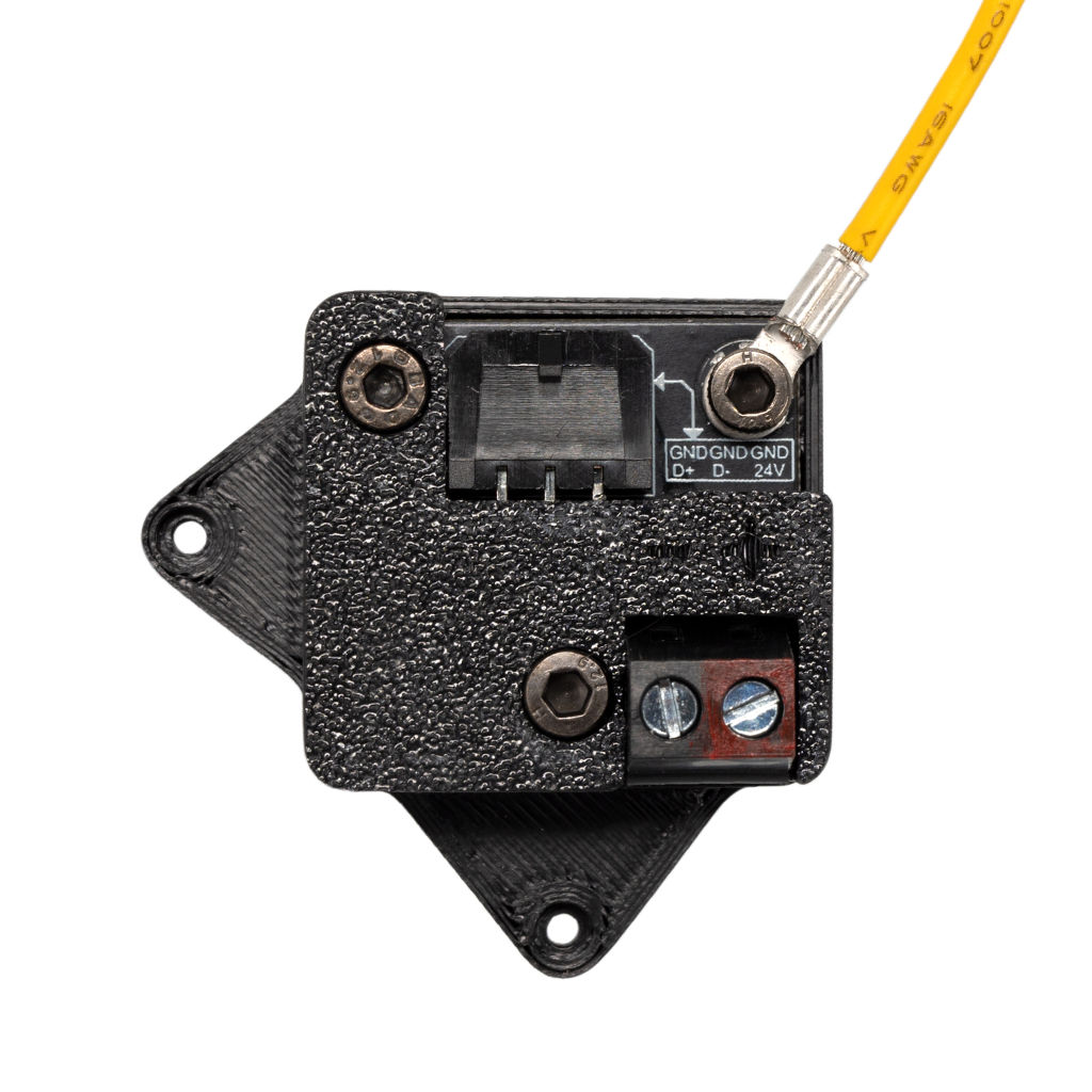
The main idea for our solution involves providing a preferred discharge path for static charge to drain to earth. This is acheived by connecting the extruder motor body to the toolboard ground, and the USB adapter ground to the printer frame - creating a continuous discharge path from the extruder motor body, through to the toolboard, umbilical cable, USB adapter, and finally frame/earth.
The Nitehawk toolboard and USB adapter board now feature a dedicated grounding points. The new kits now also provide grounding cables to connect the toolboard to the extruder motor and the USB adapter to the frame respectively. Refer to the toolboard cable routing path below. Note how the connector is bent at and angle on the motor end- this prevents interference with the cable chain anchor.
Below shows how the grounding cable is connected to the USB adapter.
¶ Firmware Setup and Update
The firmware for Nitehawk consists of two components: Katapult and Klipper. Katapult is a bootloader designed specifically for Klipper, it ensures that the software on the STM32 MCU boots up smoothly and allows for easy updating of the Klipper firmware. You can learn more about Katapult here. Klipper is the main firmware that runs on the STM32 MCU, you can learn more here.
Your Nitehawk will come shipped with both Katapult and Klipper installed. Ideally, you will only ever need to occasionally update the Klipper firmware and never have to touch Katapult. If the Katapult bootloader was erased or is not present for any reason, you can check this section for instructions on how to reupload Katapult.
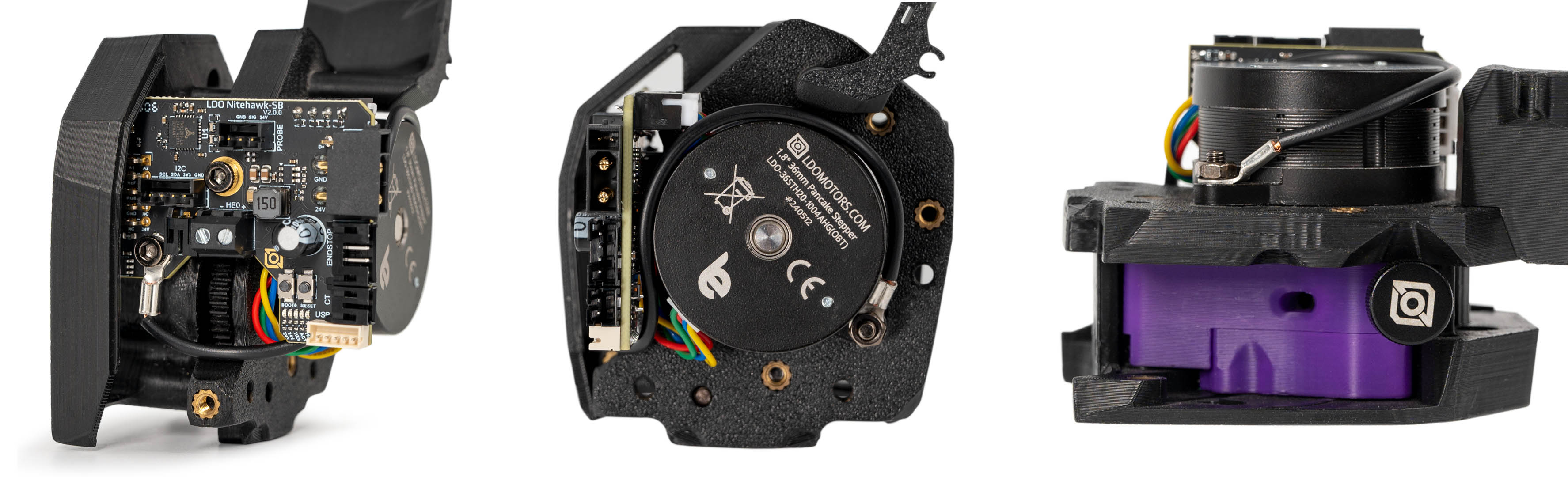
¶ Hardware Setup
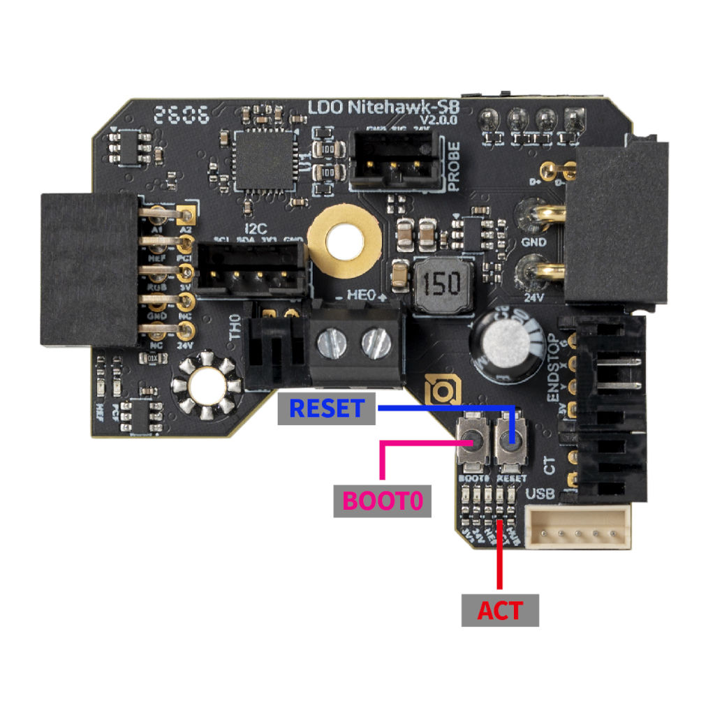
No special setup is required for installing either Klipper or Katapult. Nitehawk simply needs to be hooked up as it operates normally in your 3D printer, with the toolboard connected to your Klipper host device (e.g. Raspberry Pi) via the USB adapter board. You also need access to the two buttons (RESET and BOOT0) on the toolboard, this is normally done by moving the toolhead to the front and opening the toolhead cover. Also note the five LEDs (3V3, 24V, HE0, ACT, HUB) below the buttons - the forth LED from the left is the ACT indicator light, which will be important later. Reference the photo below to find the buttons and LEDs.
¶ Compiling Klipper Firmware
The following instructions are for compiling and upload new Klipper firmware to your Nitehawk toolboard. You need to perform these steps if you want to update your klipper firmware to the newest version or if you are doing a fresh install and just uploaded Katapult (see the previous sections). Before compiling the firmware, you will need to have Klipper already installed on your host device (e.g. Raspberry Pi).
- Log on to your Klipper host via SSH, windows users can use putty or any other SSH client. Mac and Linux users can simply connect with the
sshcommand in their command line terminal. Run the following commands to open the firmware configuration interface:
cd ~/klipper
make menuconfigIn the configurator, Enable extra low-level configuration options, choose STMicroelectronics STM32/STM32G0B1, match the rest of the settings with the screenshot below:
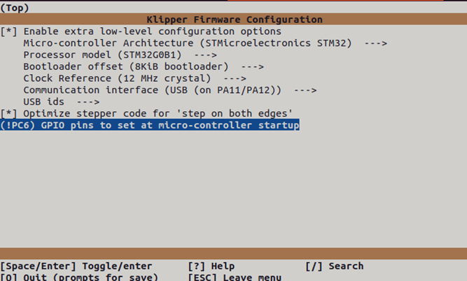
- Most importantly, make sure you set the
8KiB bootloaderoffset. Otherwise you will erase the Katapult bootloader! - Optionally setting !PC6 at micro-controller startup will make the ACT LED up on startup, this gives you an idea if your klipper firmware is running properly.
- Enter
Qto quit and confirm withYes when prompted to save. And run the following to generate the firmware file:
make clean
make A firmware file called will now be generated and can be located in the directory ~/klipper/out. You are now ready to upload this firmware to the Nitehawk toolboard. The recommended method is uploading via the make flash command.
¶ Uploading Klipper (via make flash)
- Run
ls /dev/serial/by-idto find the USB ID of your Nitehawk toolboard. The USB ID should have a format similar to this:usb-Klipper_stm32g0b1xx_1234567890000000-if00. - Run the following commands. This will install the
python,pip, and thepyserialpython module if it is not present. You may receive anerror: externally managed environmentwhen running the last command. This simply meanspyserialhas already been installed and you may move on to the next step.
sudo apt install python3 python3-pip
pip install pyserialRun the following commands to upload the firmware to the MCU directly:
cd ~/klipper
sudo service klipper stop
make flash FLASH_DEVICE=/dev/serial/by-id/<your USB ID>
sudo service klipper startIf you encounter any connection issues after flashing the new firmware, reboot your printer. Your frame PCB should now have the newest firmware. If the flashing process failed, you may want to try using the the second method and upload Klipper via Katapult
¶ Uploading Klipper (via Katapult)
In this section we will use an alternative method to upload klipper firmware using the Katapult bootloader. If your toolboad is missing the Katapult bootloader for any reason, you should follow the next section to install it first.
- First we will check and install the Katapult package (if necessary):
test -e ~/katapult && (cd ~/katapult && git pull) || (cd ~ && git clone https://github.com/Arksine/katapult) ; cd ~To upload Klipper, we will use a Python script to communicate with the Katapult bootloader inside of the Nitehawk Toolboard. First, we will first need to setup a Python3 environment. Run the following:
virtualenv -p python3 ~/katapult-env
~/katapult-env/bin/pip3 install pyserial This creates a Python 3 environment in the location ~/katapult-env/ and installs the module pyserial which is required to run the upload script.
- Now we must force Nitehawk to enter the Katapult bootloader and obtain the USB serial address. Start by quickly double clicking the RESET button, you should see the ACT light blinking slowly.
- Next run
ls /dev/serial/by-id/. You should see something likeusb-katapult_stm32g0b1xx_A1234567898D1234-if00- note that the address contains the wordkatapult. If not, this means either your Nitehawk did not have Katapult installed or you did not enter the Katapult bootloader properly. Copy the address down for the next step, do not exit the bootloader yet. - Finally run the following but substituting the address with the one you obtained in the previous step. If everything was correct, you should see some write and verification progress followed by
Flash Successat the end.
~/katapult-env/bin/python3 ~/katapult/scripts/flashtool.py -d /dev/serial/by-id/usb-katapult_stm32g0b1xx_A1234567898D1234-if00 As a final verification, run ls /dev/serial/by-id/. you should see a Klipper USB serial address in the form of usb-Klipper_stm32g0b1xx_E1234567A12D9835-if00.
¶ Installing the Katapult Bootloader
In this section we will compile and upload the Katapult Bootloader. Note that your Nitehawk toolboard normally ships with Katapult pre-installed and you only need to perform the following operations if Katapult was inadvertently overwritten or lost.
- Login to the Raspberry Pi. We will check and download the Katapult package (if necessary):
test -e ~/katapult && (cd ~/katapult && git pull) || (cd ~ && git clone https://github.com/Arksine/katapult) ; cd ~Now we will configure need to configure some options:
cd ~/katapult
make menuconfigThis will bring us to the configuration menu. Make sure to set the options as below:
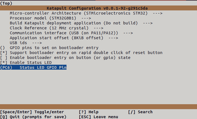
- Enter
Qto quit and confirm withYes when prompted to save. next run the following command to compile and generate the Katapult binary files:
make clean
make A binary file called katapult.bin will now be created in the location ~/katapult/out/. Our next job is to upload this file into the STM32G0B1 MCU on the Nitehawk toolboard.
- We now need to reboot the Nitehawk toolboard into system boot mode. This is done in three steps:
- Press and hold both the RESET and BOOT0 button.
- Release the RESET button
- Release the BOOT0 button
- If done correctly, your Nitehawk should now have entered DFU mode. Run the command
lsusbto confirm. You should see something likeBus 001 Device 023: ID 0483:df11 STMicroelectronics STM Device in DFU mode. If you did not get the previous output, this means either Nitehawk didn't enter DFU mode or there is a problem with the physical connection between the Raspberry Pi and Nitehawk. - We are now finally ready to upload Katapult. Run following commands:
sudo apt install dfu-util
sudo dfu-util -a 0 -s 0x08000000:leave -D ~/katapult/out/katapult.bin If everything went smoothly, you should now be able to see the ACT light located below the BOOT0 button blink slowly. To double check that Katapult is installed, run ls /dev/serial/by-id. You should see something like: usb-katapult_stm32g0b1xx_A1234567898D1234-if00which is USB serial address of Nitehawk running Katapult. A few small details to note here:
- You will only see this address when Nitehawk is in Katapult bootloader mode and not in system boot mode or when Nitehawk is normally running Klipper.
- You can force Nitehawk to enter the Katapult bootloader by quickly double clicking the RESET button on the toolboard. The ACT light blinks slowly in this mode as previously mentioned.
- You will need enter the Katapult bootloader and the Katapult USB serial address to upload Klipper.
- By following the above instructions, you will have uploaded Katapult but erased all other firmware, including any previously installed Klipper firmware.
- Exit the Katapult bootloader by single pressing the RESET button, normally you would enter Klipper firmware. Since you just erased Klipper, you will just re-enter the Katapult bootloader.
- you are now ready to compile and upload Klipper - see the previous section here.
¶ FAQ
Q. I have an LDO V2.4/Trident Kit with the original Nitehawk-SB, what parts are resuable?
A. The umbilical cable and pinout is exactly the same as the original Nitehawk-SB, so you can continue to use that. The USB adapter PCB also has minimal changes and can be reused. The fan adapter PCB now has a different gendered header so cannot be reused.
Q. Can I use the provided cable in a drag chain or umbilical setup?
A. Yes! The included toolhead cable is drag chain rated but also easily set up for umbilical use.
Q. I see that there is a 4pin XY endstop connector, what is that for?
A. Since there is no longer any breakout PCB, the XY endstop can instead be routed a short distance through the X drag chain and into the toolboard. Of course, you can also opt to route directly back to the mainboard or just use sensorless homing.
Q. What is the ACT LED for?
A. That’s just a controllable LED, you can find it in the klipper config we provide. We enable this LED out of factory and use this as an indicator of whether klipper firmware is running.