This guide contains directions for wiring up a Voron 0S1 using the pre-made cables included in the LDO kit. Important! Mains wiring should only be performed by certified personnel trained in local regulations and safety standards. If during any step of this guide, you find the images to be unclear, you can always view the high resolution source files here.
¶ Wiring The Kirigami Bed
The V0S1 kit includes a Kirigami bed mount as well as necessary cables to conveniently install or remove the heated bed. The Kirigami kit also includes a neopixel front light that provides controllable RGB lighting. Follow the guide here for wiring up the Kirigami heated bed.
¶ Wiring the Picobilical Toolhead PCB
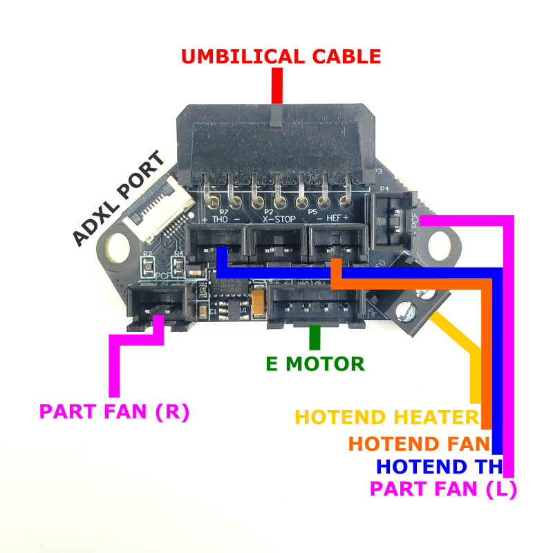
The toolhead can be wired up as soon as you finish assembling it. The following diagram shows the approximate wiring path you can use for routing each of the toolhead components.
- Note the labelled ADXL port - this port is used for input shaping but should be left unplugged except for when you need to perform input shaper tuning.
- If you find the E motor cable to be too long: make sure that the motor wire is oriented upwards, the motor can then be wrapped around from the left or right side of the motor body before being plugged in.
- The 14pin umbilical cable can be plugged in at the very end of the printer build. It can also be unplugged any time you need to perform maintenance on the toolhead. But make sure to unpower the printer first!
¶ Wiring The Deck Panel
¶ Preparing The AC Inlet
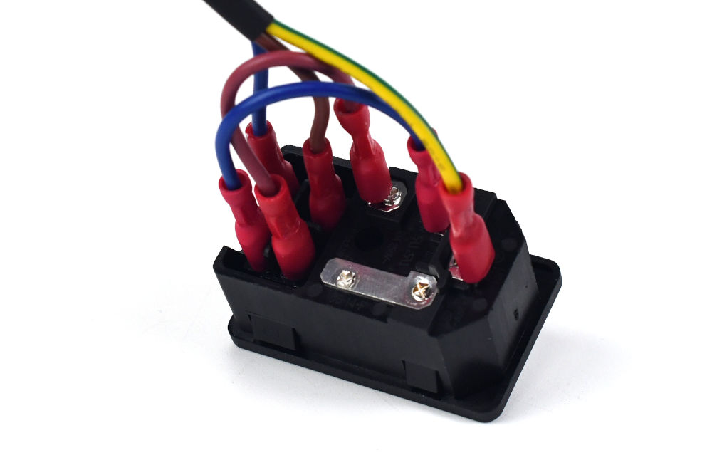
Your kit should include a pre-wired AC inlet. Double check that the wiring correct, the final layout should be as follows:
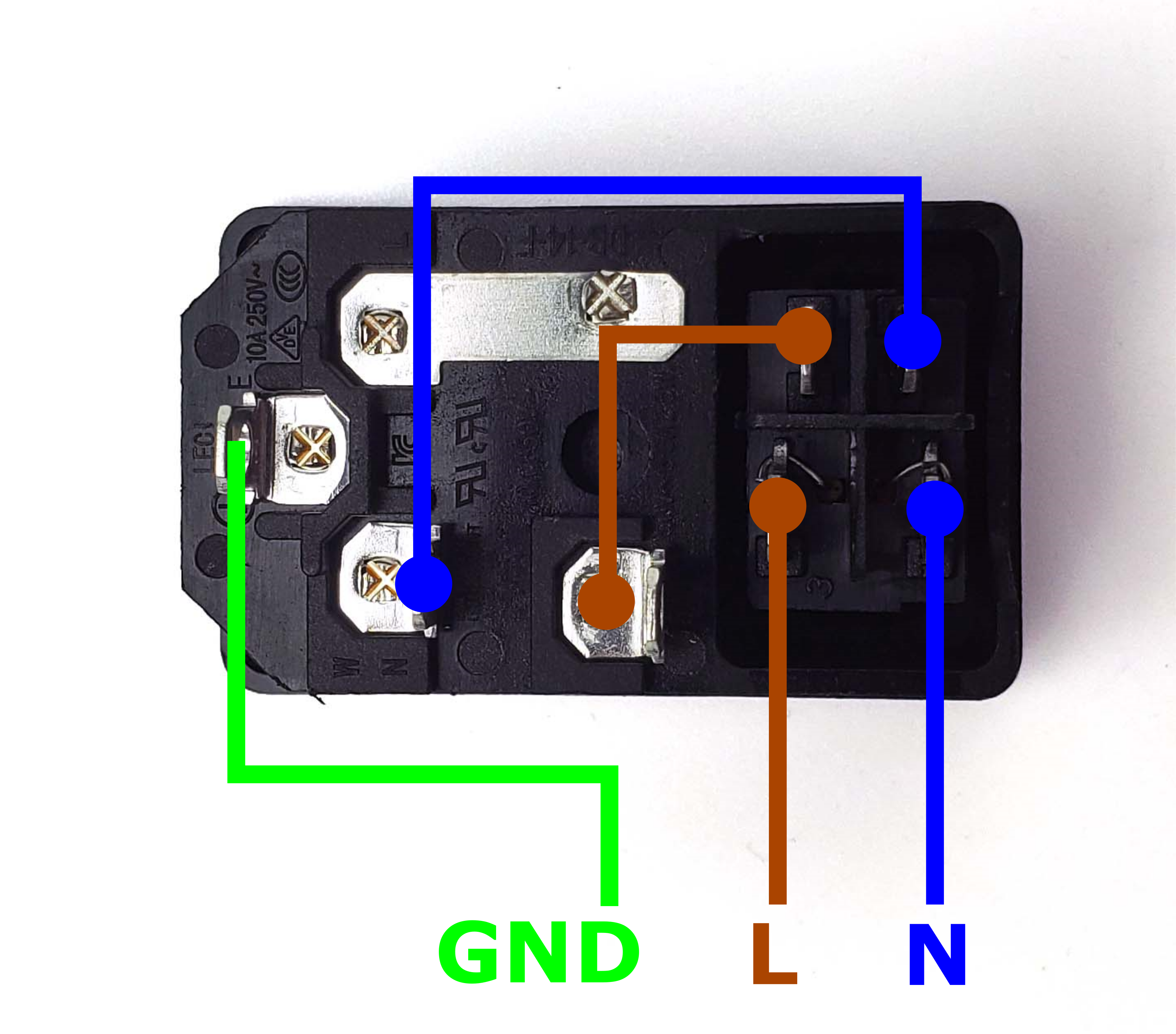
Take the inlet cable included in the kit and attach the wires using the above layout as reference. When wired correctly, your live wire will be protected by a fuse, and the switch on the front side of the inlet will operate correctly (lights up when switched on).
¶ Preparing the Power Supply
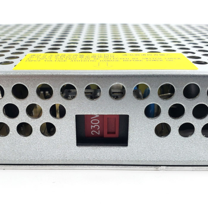
Your kit includes a compact 24V 200W power supply unit. Check for a switch on the side of the power supply to select between 115V or 230V. Flick the switch to the correct value before powering it on! Failing to do so can destroy the power supply! If you received a power supply with Power Factor Correction (PFC, model #LMF200-23B24), then there is no switch to worry about.
¶ Placing the Power Supply
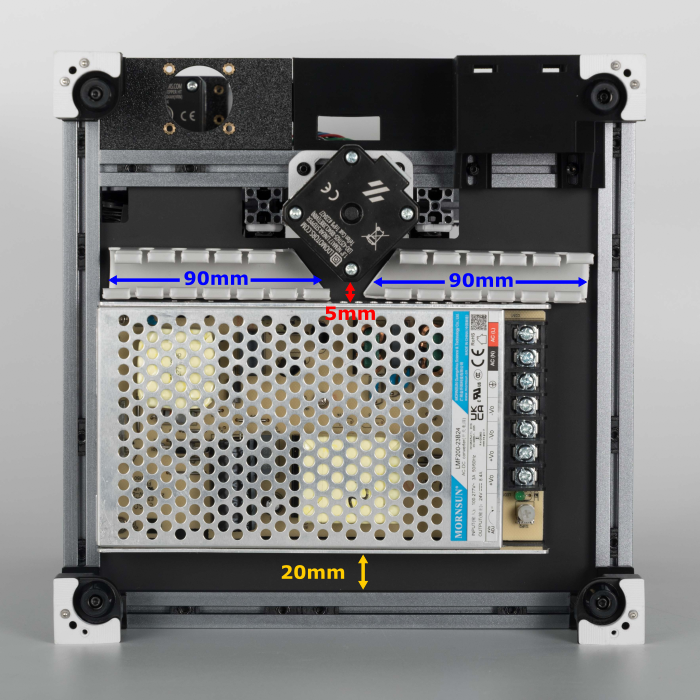
Add a few strips of VHB tape to the underside of the 24V power supply. Place the power supply and wire duct in the location shown below while keeping mind of these points:
- Make sure to leave a small gap of about 20mm between the front extrusion and the deck panel - this is to provide clearance for a display.
- You still need leave a small gap of 5mm between the Z motor and Power Supply so that cables can be run between them.
- There will not be enough space for the wire duct to be placed between the power supply and Z motor, so you need to cut two 9cm segments and trim them diagonally at the ends as shown in the photo.
¶ Mains Wiring
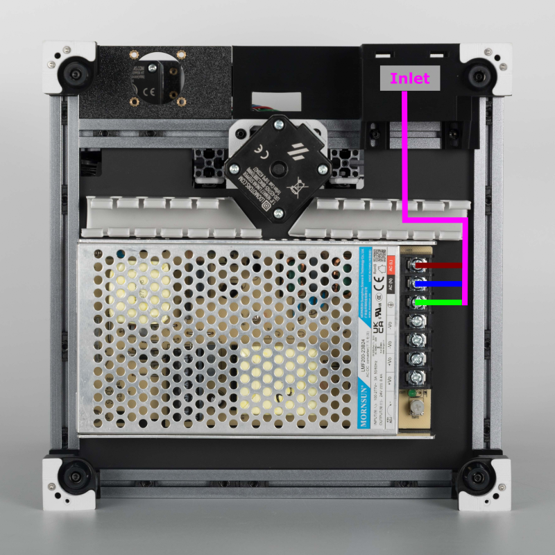
We will now connect the AC inlet to the 24V power supply. Refer to the following diagram and table:
| Name | Cable Label | Cable Colour | PSU Terminal |
| Live | L | Brown | AC(L) |
| Neutral | N | Blue | AC(N) |
| Earth | PE | Green & Yellow | ⏚ |
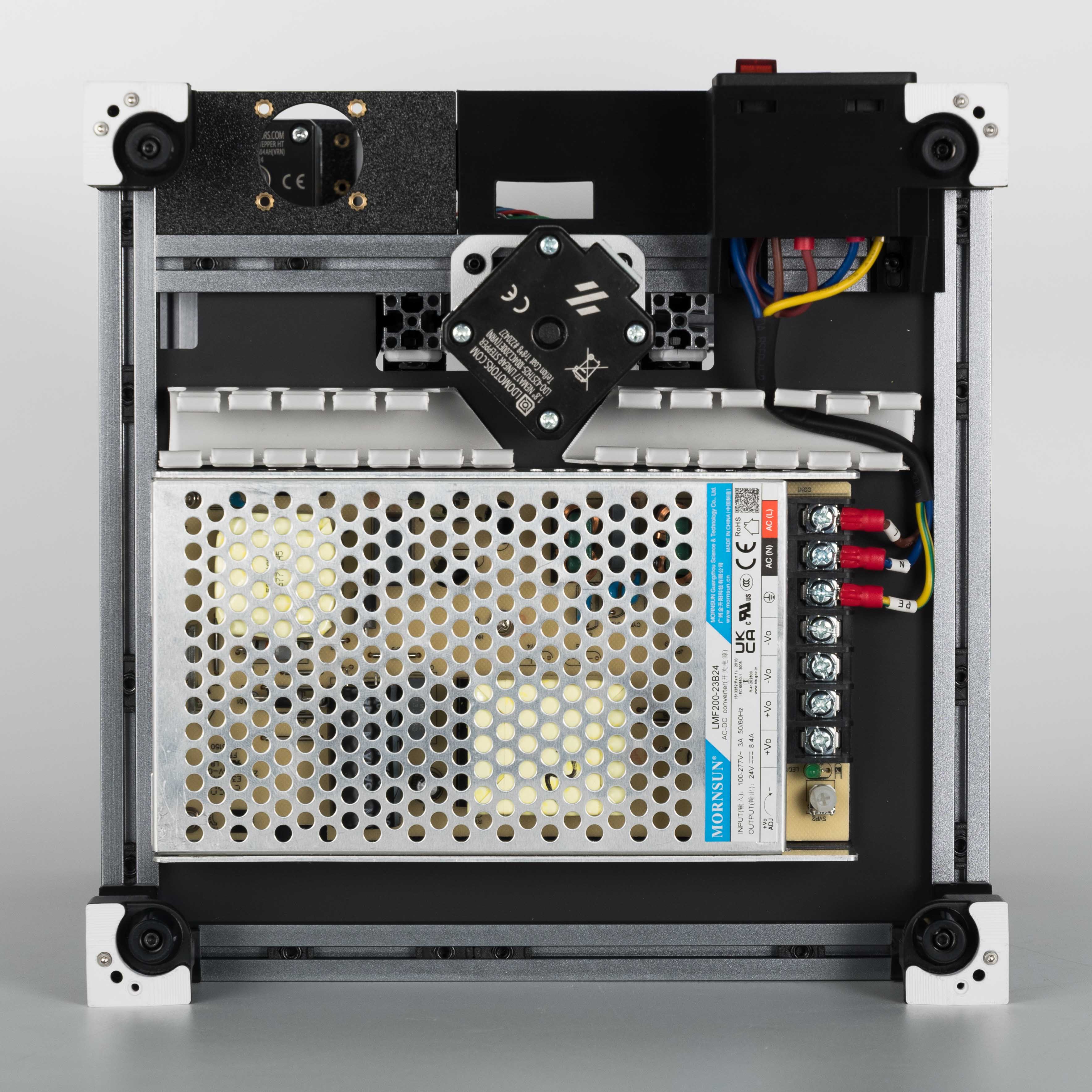
After finishing, check your work by comparing it with the high resolution photo here.
¶ Check Point #1
Before moving on to the next step, let us check the mains wiring. Incorrect wiring of AC/mains can be dangerous - therefore, always double check your work, and then triple check it once more:
- Remember to check everything without the power cable plugged into the inlet!
- Use the multimeter to check continuity between Live, Neutral, Earth - they should not be shorted with each other.
- Check again that the power supply voltage input switch (if applicable) is set to the correct value: 115V vs 230V
- After checking all of the above, plug in the power cable and switch on the inlet: The power supply should turn on and it's LED should light up.
- Switch off the inlet and remove the plug, we can now move on to the next step.
¶ Finishing Off Below Deck Wiring
In this step, we will finish wiring and routing the remaining cables below the deck panel. Follow the diagram below to route the cables.
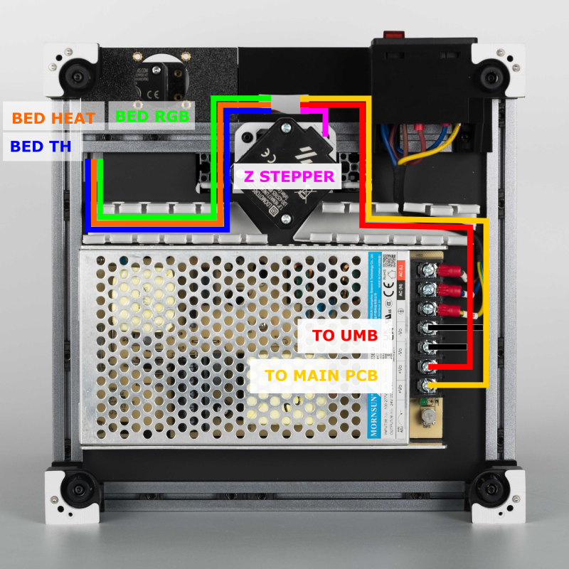
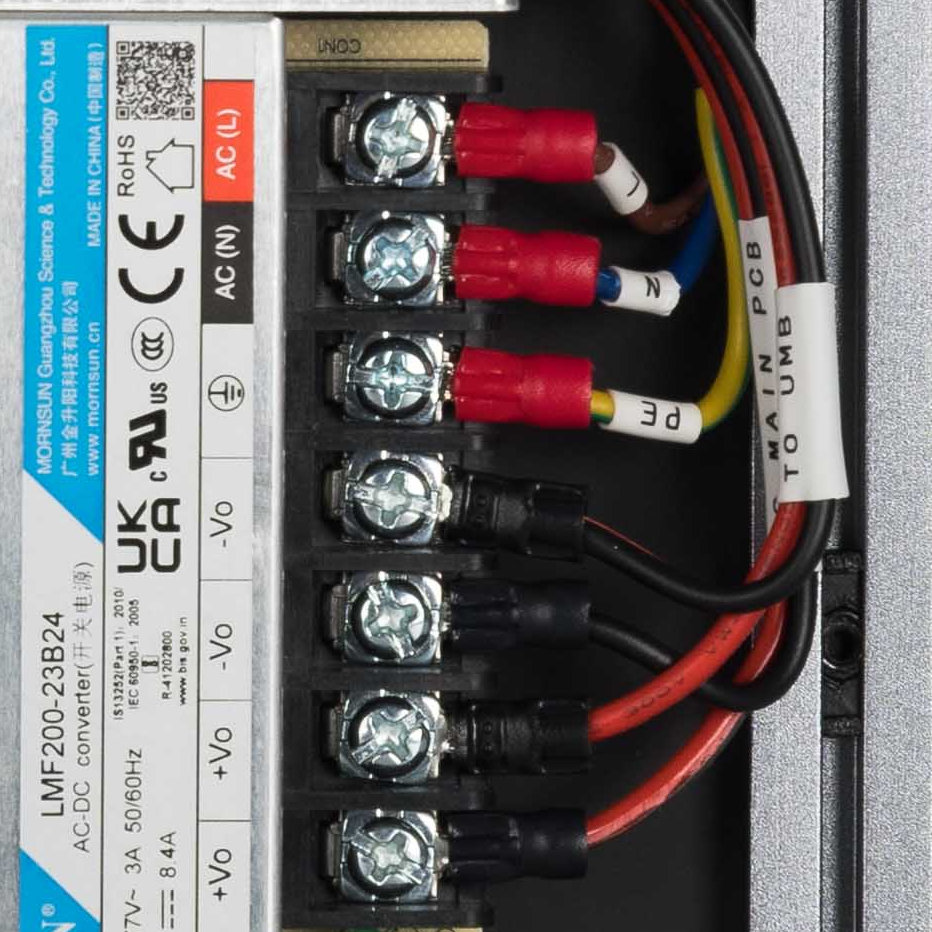
Pay close attention to the polarity of the 24V power cables - incorrect polarity can damage your PCBs. Compare your work with the close up below:
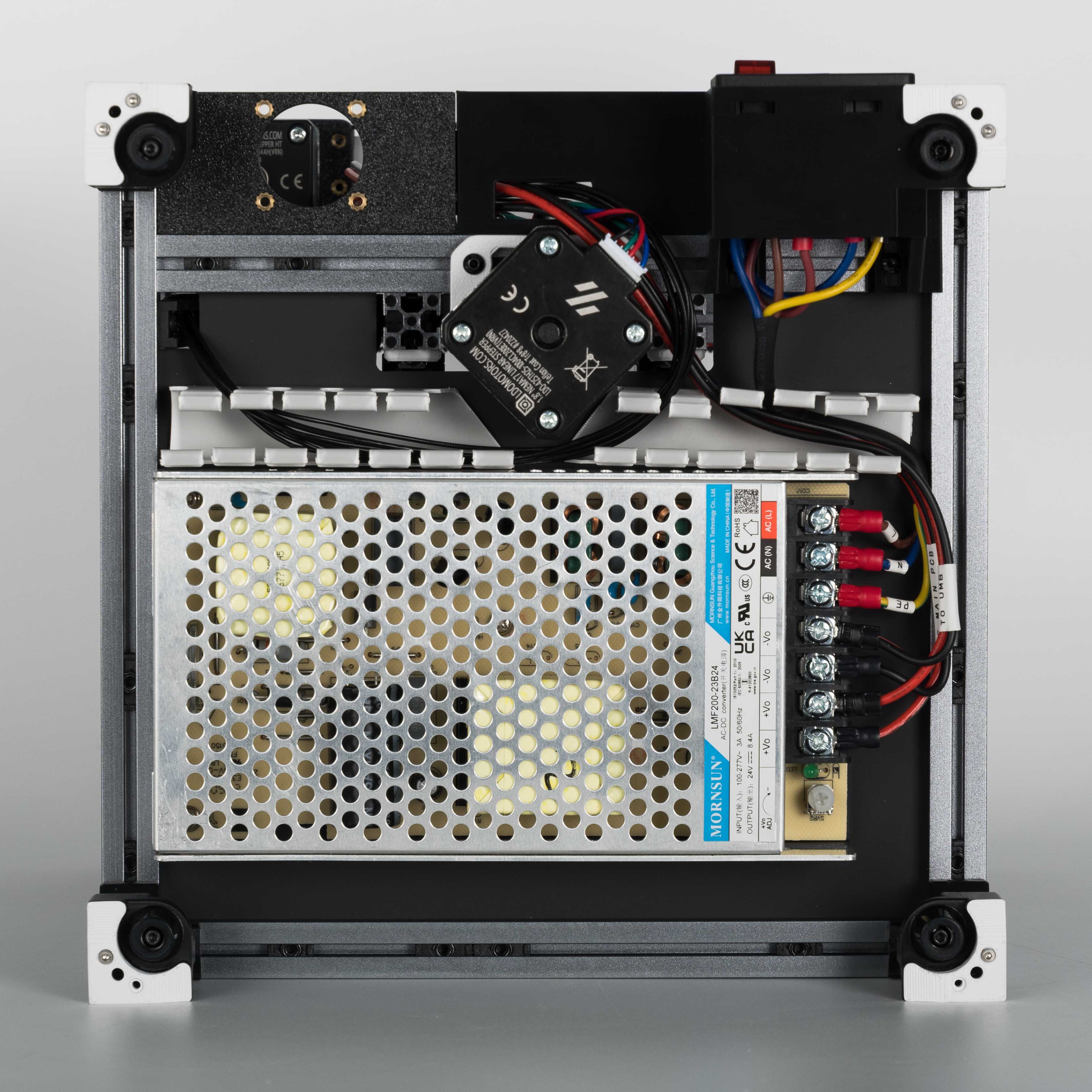
The heatbed cables can be alternatively routed from the right side of the stepper motor. As shown in the photo below.
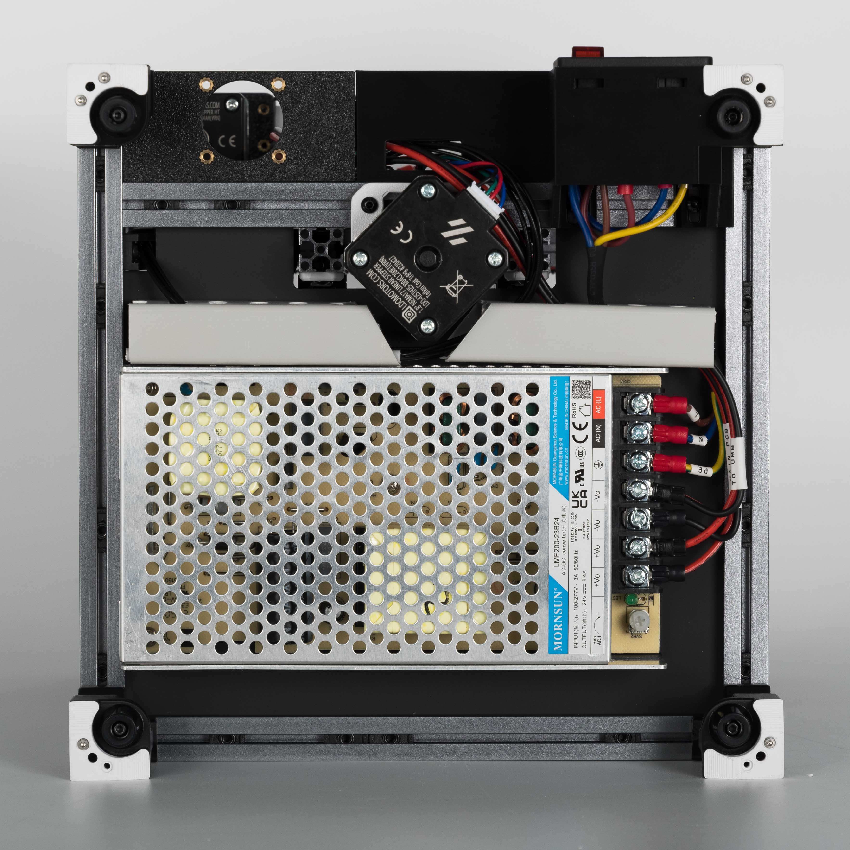
Once you are done, cover up the wire ducts. Now you have completed the deck panel wiring!
¶ Wiring the back Panel
¶ Preparing the SKR Pico
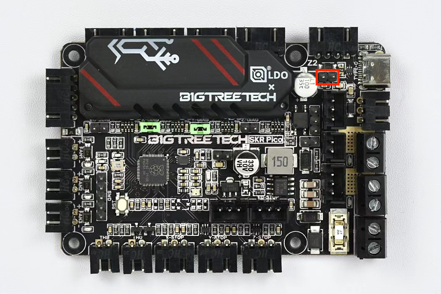
The SKR Pico has the same hole pattern as a full size Raspberry Pi, so use the printed Raspberry Pi mount on the Pico. If you plan to run sensorless homing, then add a jumper to the corresponding DIAG header. Otherwise, remove any other jumper on the PCB. It is also good practice to mark the positive terminals on the PCB with red markers - this might help you avoid any polarity mistakes later when making connections.
¶ Preparing the Raspberry Pi
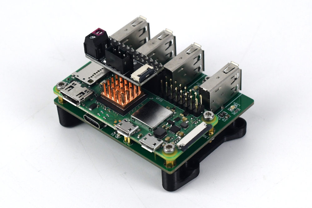
If your kit includes a Raspberry Pi Zero 2W, it will have come with a USB expander PCB. Print this mount designed specfically for the USB expander, there are two holes which accept M2x10 self tapping screws and two others that are screwed in using the brass standoffs (remove the nuts underneath).
Install the Raspberry Pi onto the USB expander using the four M2.5x4 screws provided - the Rpi will automatically be connected to the USB expander via pogo pins.
Stick the provided copper heatsink onto the main processor. Finally, add the input shaper pi hat to the Raspberry Pi header. Note that the positive power terminal on the pi hat is marked red.
¶ Preparing the Picobilical
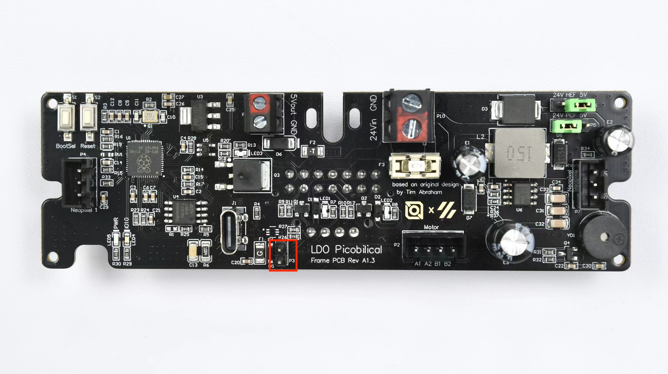
The Picobilical Frame PCB has an RP2040 microcontroller that should be pre-flashed with klipper firmware. If your picobilical was not flashed, or needs to be re-flashed with newer firmware, check here.
- Install the fan voltage jumpers corresponding to the rated voltage of your hotend (HEF) and part fans (PCF). In the photo shown below, the hotend fan is set to 5V while the part fan is set to 24V.
- Note the 2 pin header circled in red - it should not be populated with a jumper unless you neeed to flash the board using the UF2 bootloader mode.
¶ PCB Placement
Now we can place the major components behind the back panel:
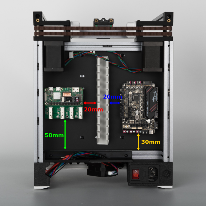
- First take the remaining length of wire duct and place it in the center of the back panel. Note that the length of the wire duct is not long enough to span the entire height of the panel - this is on purpose, you want to leave some clearance at the top and bottom of the wire ducts.
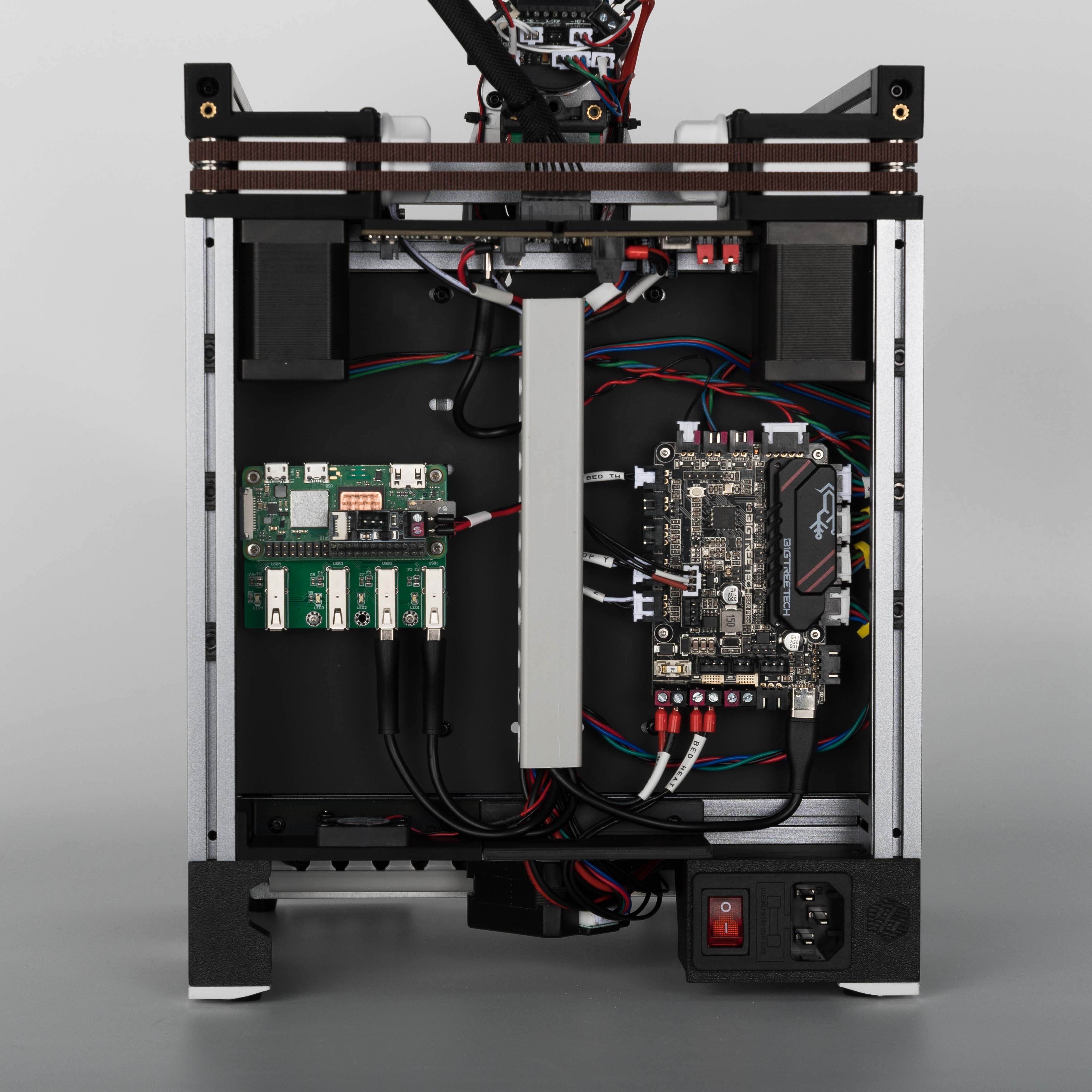
- Place the Raspberry Pi to the left of the wire duct. Note the clearances in the diagram below. If you have a full size Raspberry Pi rather than the Raspberry Pi Zero shown in the photo, make sure to orient the RPi so that the USB ports face downwards.
- Place the SKR Pico to the right of the wire duct. Again, note the clearances in the diagram.
¶ SKR Pico Connections #1
In this step we will start hooking up connections to the SKR Pico. We'll start by connecting the cables that were previously routed from the bottom. Check the port diagram of the SKR Pico here.
| Cable | SKR Pico Port Name | Notes |
| BED TH | THB | The thermistor cable has no polarity |
| BED RGB | RGB | Check how to install the plastic housing here |
| BED HEAT | HE | The bed heat cable has no polarity |
| 24V IN | POWER | Double check the polarity! Red is the positive side. |
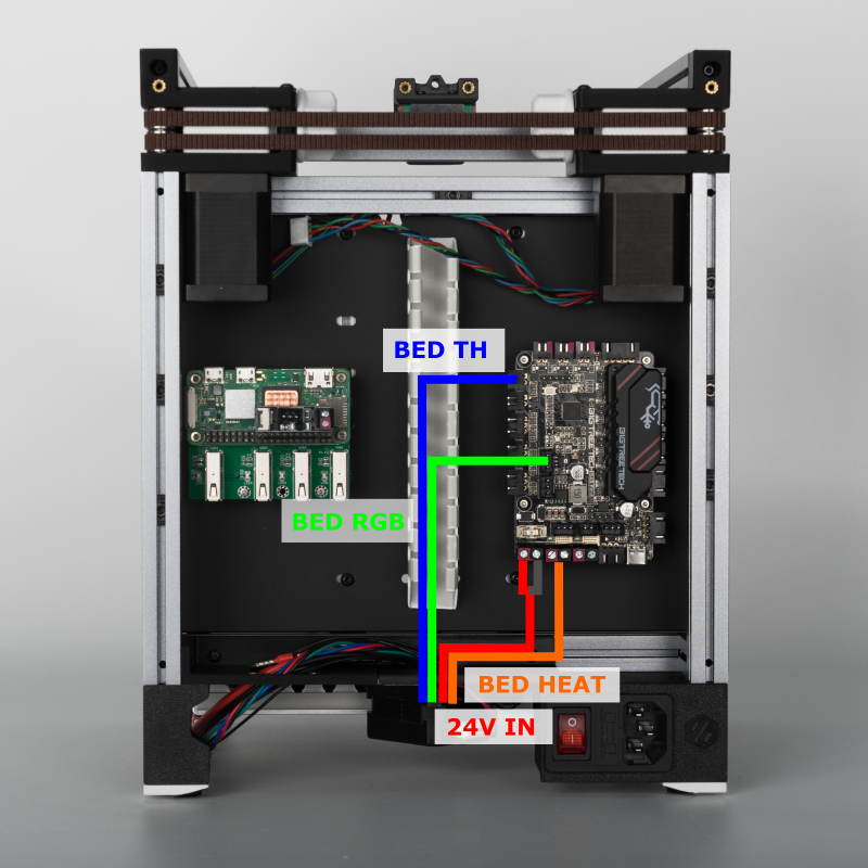
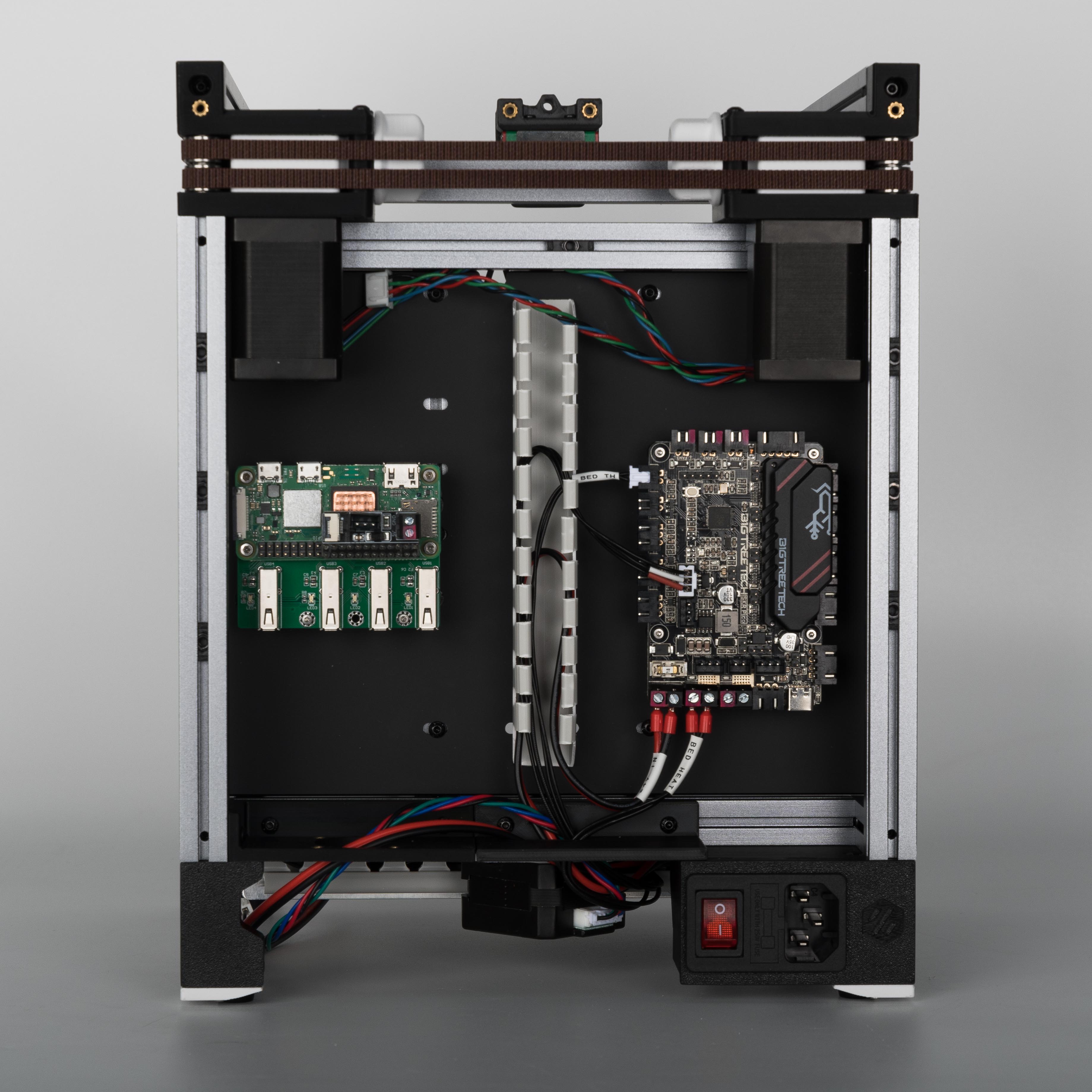
The result looks like this.
¶ SKR Pico Connections #2
In this step, we will connect the stepper motors and endstops to the SKR Pico. Refer to the table and diagram below.
| Cable | SKR Pico Port Name | Notes |
| A STEPPER | Y (STEPPER) | |
| B STEPPER | X (STEPPER) | |
| Z STEPPER | Z1 (STEPPER) | |
| ENDSTOP Y | Y-STOP | |
| ENDSTOP Z | Z-STOP |
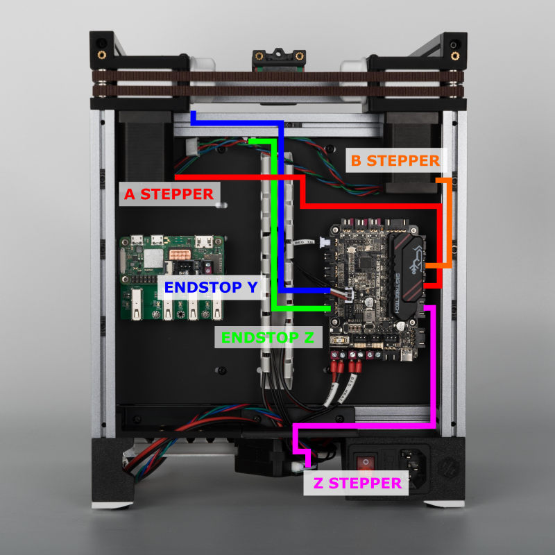
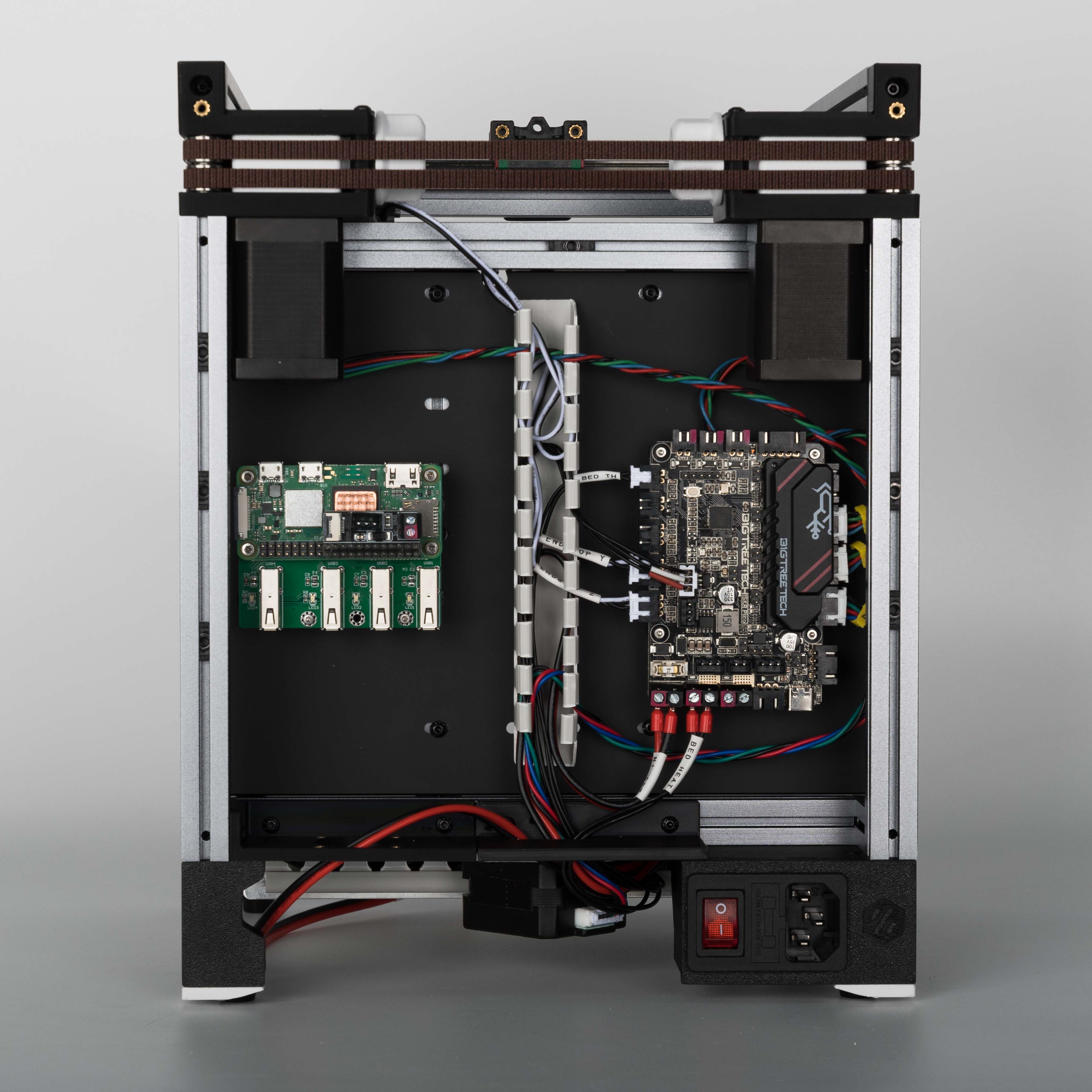
The result looks like this.
¶ Installing the Picobilical
In this step, we will install and connect the Picobilical Frame PCB. Before installing the Picobilical Frame PCB, we recommend connecting the cables first as the screw terminals are harder to access after the PCB is installed. It is also easier to check for polarity mistakes before the PCB is installed.
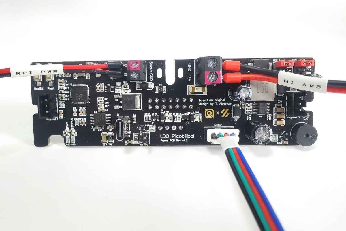
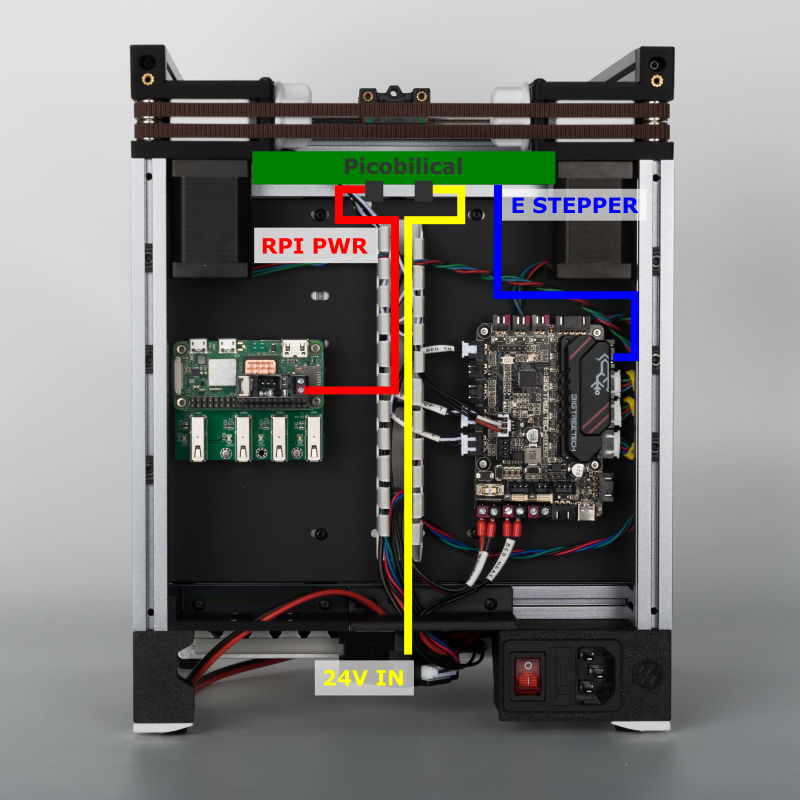
With the cables pre-attached, install the Picobilical Frame PCB where the acrylic motor panel usually goes. Don't forget to print and install the PCB cover plate! Route the cables according to the diagram below.
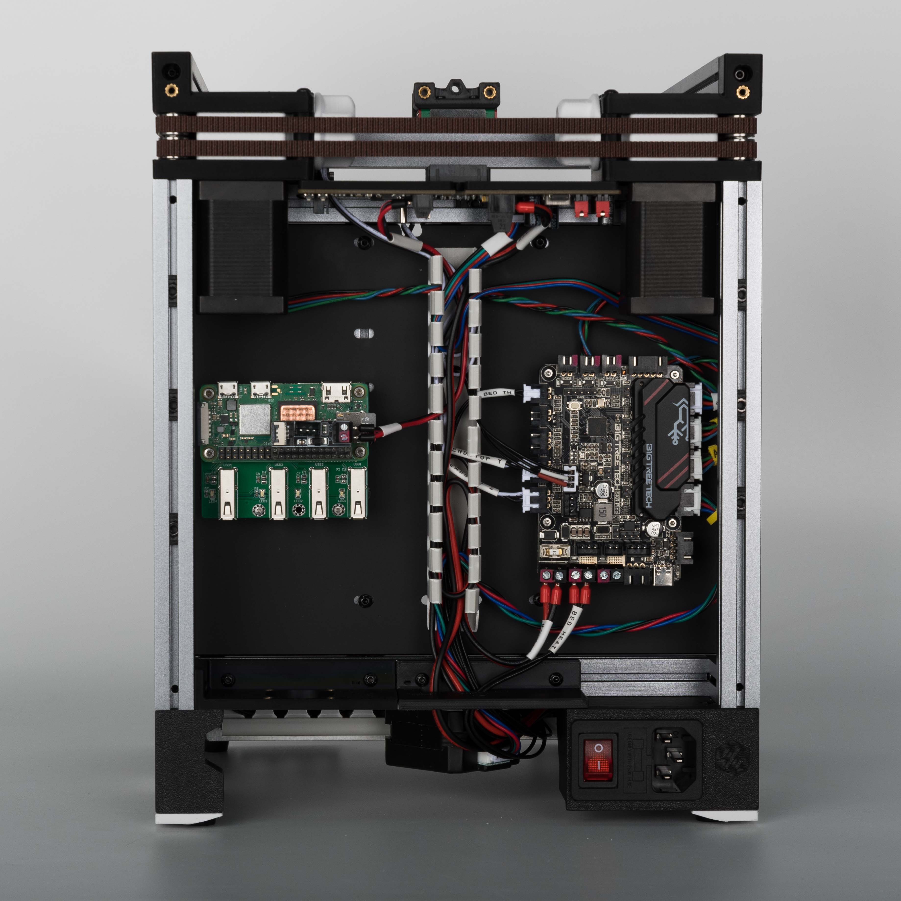
The result looks like this.
¶ Installing The USB Cables
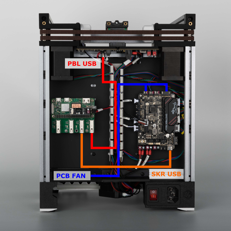
In this step we will, connect the USB data cables from the Picobilical and SKR Pico to the Raspberry Pi. If you chose to install the bottom PCB fan mount, we will now install the fan as well.
- The USB cables for both PCBs can be plugged into any USB port of the Raspberry Pi.
- If you use a 24V fan, plug it directly into FAN3. If you are using a 5V fan, plug the negative fan pin into the FAN3 port and the positive fan pin into one of the 5V pins of the SKR Pico (the 5pin connector beside FAN1 has two 5V pins).
- If you have a 5V fan from an old LDO V0.1 kit, it will already have a split two connector setup that will work, no modifications needed!
The result looks like this.
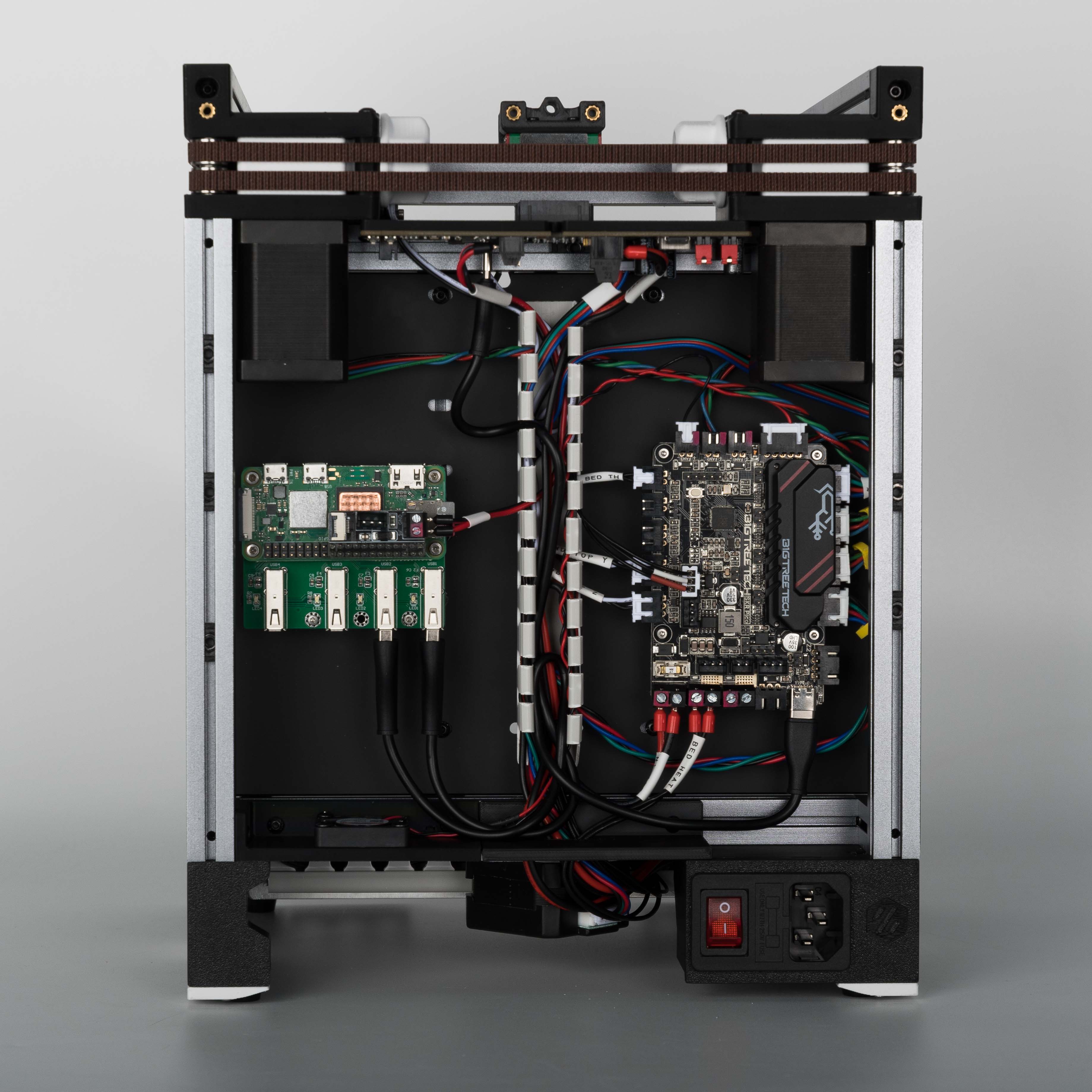
¶ Finish Line
Congratulations! Insert the Umbilical cable from the Toolhead PCB to the Picobilical Frame PCB, cover up the wire duct, and now you are done!
