This guide contains directions for wiring a Rev. C Voron Switchwire using the pre-cut, pre-terminated cables included in the LDO kit. Important! Mains wiring should only be performed by certified personnel trained in local regulations and safety standards.
¶ Pre-Wired Items
The following items have been soldered to cables for your convenience. In theory, there is no need to solder or crimp anything:
- X Endstop
The following items should have pre-cut lengths, labels, and crimped connectors:
- Heatbed Thermistor
- Part Cooling Fan
- Hotend Fan
- Z Probe
Certain stepper motor cables are purposely left longer than needed for people with different setups. You may choose to cut them or leave them as is during wiring.
¶ Cable Routing during Mechanical Assembly
While much of the wiring can be done after the the mechanical components of the printer is fully assembled, certain cables are much easier to route during assembly. We recommend reading this section before you begin assembling your printer in order to avoid any unnecessary disassembly.
¶ A/B(X/Z) Motor and Toolhead Cable Routing
We recommend routing the XZ motor and toolhead cables at the same time you install the deck panels - The opening is too small to insert the connector directly through the deck opening. Note that the stepper motor cables have similar looking but different connectors on each end. The 6 pin PH connector should be situated above the deck panel while the 4 pin XH connector should be situated below the deck panel. There should be a single motor cable that is lengthier (70cm) than the others, route this cable through the left opening in the deck panel (when looking directly at the front of the printer).
¶ Y Carriage
First let's prepare the Y cable chain: grab the shortest of the 3 cable chains (15 links, not including the end links). Fit the heatbed power cable and bed thermistor extension cable through the cable chain (keep in mind that you can open the links!). Make sure the following connectors are all on the same end of the cable chain: ring terminals (heatbed power), male JST XH (heatbed TH). Refer to the following pictures
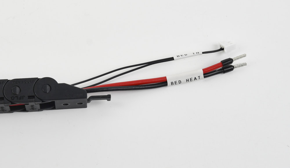
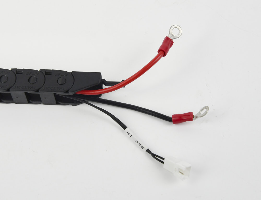
You are now free to install the Y cable chain once the Y carriage is assembled. Make sure the end with the connectors mentioned previously is attached to the Y carriage. Refer to the following picture for orientation:
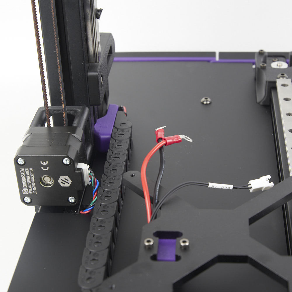
¶ Heated Bed
Before installing the heated bed onto its Y carriage, you will need to attach the bed thermistor to the underside of the heatbed PCB. Gather the following items:
- Heatbed thermistor, this thermistor should have a bare glass bead tip instead of a metal barrel shroud (used in the hotend).
- Polyimide Tape, the kit includes a few pieces of this clear yellow tape precut to a square shape.
- Aluminium Tape, the kit includes a few pieces of aluminium tape precut to a square shape.
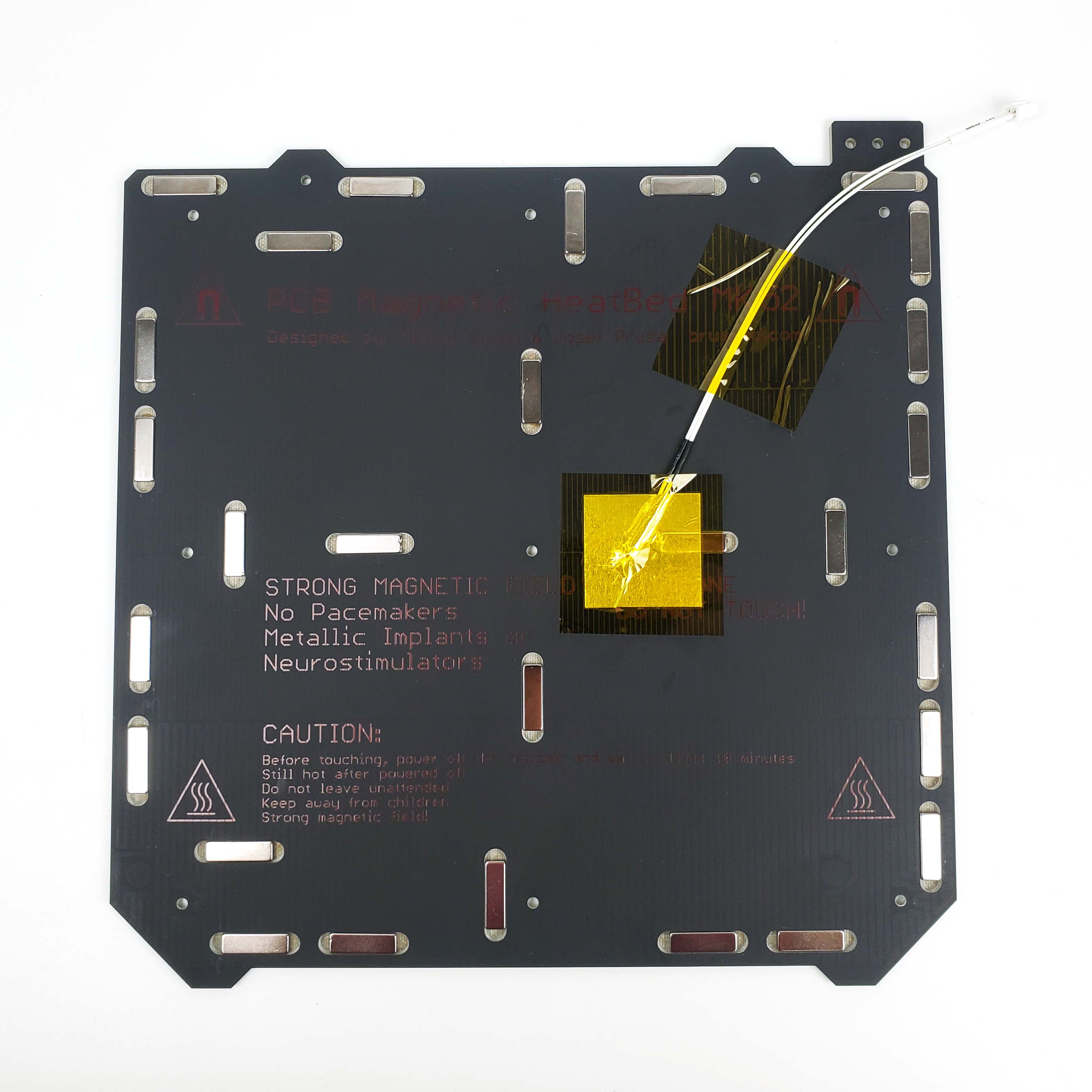
Place the heatbed topside down. Look for a small circle just right of the center. Position the thermistor glass bead tip within this circle and orient the thermistor cable so that the connector is roughly around the top right corner of the heatbed. Apply a small amount of thermal paste to the thermistor tip(your hotend usually comes with a small bag of thermal paste) and then cover with piece of aluminium tape and polyimide tape. Make sure that thermistor tip is in contact with the heatbed and also is not able to wiggle under the two layers of tape. Also take care not to cover over the hole at the center of the heatbed. Next use another piece of polyimide tape to fix the thermistor cable. Refer to the following picture for the final result:
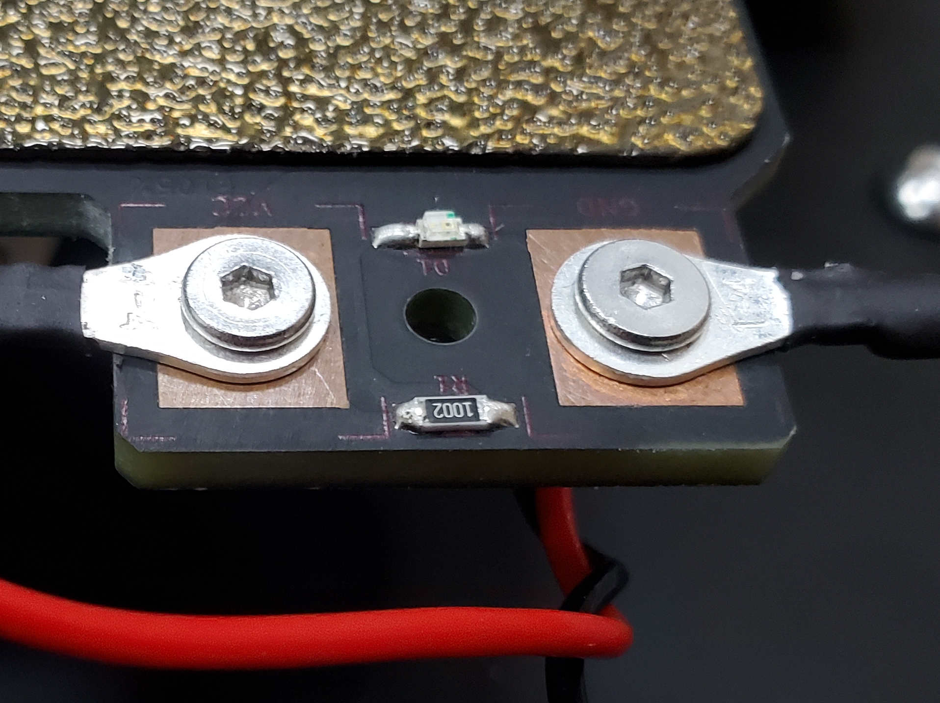
When attaching the power cables to the heatbed, check for signs of oxidation on the PCB pads. If the copper pads look tarnished or dull, use a piece of sand paper and lightly sand the pads. To fasten each ring terminal to the pads, you will need an M3x8 screw, and M3 nyloc nut. Important! make sure the ring terminal makes direct contact with the copper pad. If you plan on enclosing your printer, orient the ring terminals so that the cables face outwards. The final result should look like this:
¶ Toolhead Wiring
The follow section covers cable routing/wiring related to the stealthburner toolhead.
¶ X Endstop Routing
The x endstop cable comes with the plastic housing removed. We recommend installing the plastic housing until after correctly routing the cable through the carriage frame. Refer to the following picture.
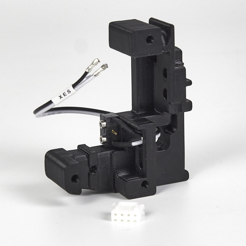
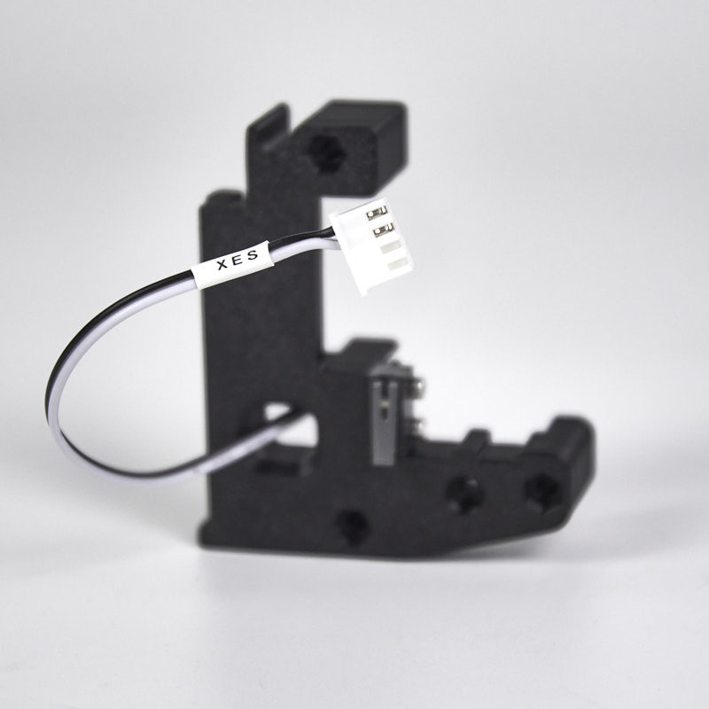
The provided plastic housing is a 4pin JST-XH connector, two of the pins are intentionally left unpopulated. Refer to the following picture to correctly insert the pins from the endstop cable into the plastic housing.
¶ Insulating the Z Probe
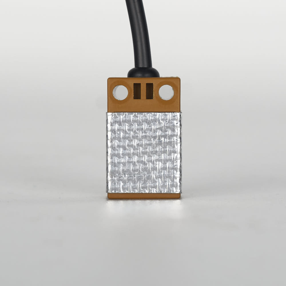
Our kit comes with a small strip of fiber glass tape. This tape is used to help insulate the Z probe from radiative heat from the the hotend. We recommend covering the front and sides of the probe with at least 2 layers of this tape. Do not cover the back or the bottom of the probe, if you have problems triggering the probe, try removing bits of the tape as it may be interfering with probe sensing. Optional: consider cutting an opening in the tape, around the LED of the Z probe - this will allow you to see the LED light up when the Z probe is triggered.
¶ Stealthburner Wiring
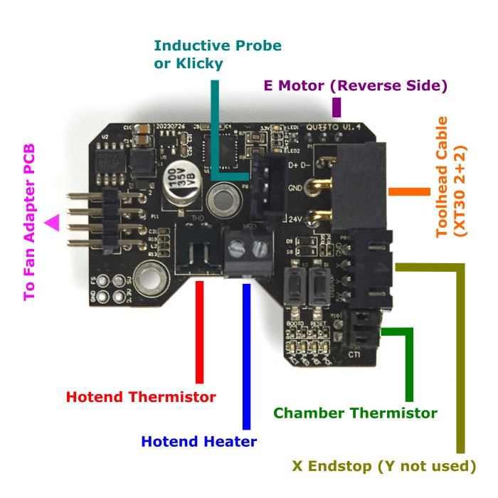
This kit contains parts to build the Stealthburner + Clockwork 2 toolhead. A USB toolhead PCB is provided to greatly simplify wiring. The main toolhead PCB attaches to the sides of the Clockwork 2 extruder. Use two M3x8 screws to install the PCB to the Clockwork 2 extruder. Remember to place a spacer between the PCB and the extruder.
- Connect the inductive probe or Klicky cable to the PROBE port. Note that for Klicky, the 24V pin is not connected. If using the TAP probe, make sure the probe PCB is compatible with 24V.
- Connect the hotend heater to the screw terminal connector - polarity does not matter here.
- Connect the hotend thermistor to the TH0 port.
- Connect the external thermistor to the port labelled CT. The chamber thermistor provided in the kit is labelled with “CT”. Remember to use this cable cover which comes with a holder for the chamber thermistor.
- Connect the extruder motor to the E MOTOR port located at the back of the PCB.
- Connect the X endstop to the XY endstop port (the Y and 5V pins are not connected).
- Attach the USB toolhead cable to the XT30(2+2) port - you should do this after installing the Clockwork 2 extruder onto the X carriage.
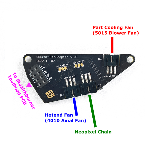
The fan adapter PCB attaches to the rear of the Stealthburner main body. Use two M3x6 screws to install the PCB directly on the back of the 5015 fan.
- Connect the 5015 Blower Fan to the port P4. If you are using your own fan, use the polarity labelled on the PCB to crimp a 3pin JST-PH2.0 connector to your fan cable.
- Connect the 4010 Axial Fan to the port P2. If you are using your own fan, use the polarity labelled on the PCB to crimp a 3pin JST-PH2.0 connector to your fan cable.
- Connect the Neopixel Chain to the port P3.
- The 2x8 headers on the two PCBs connect to each other when your install the Stealthburner main body to the rest of the toolhead - this allows you to easily attach and detach the stealthburner when performing maintenance or upgrades. Make sure the two headers line up properly each time they are connected.
¶ Preparing the Electronics
¶ The Mainboard (SKR mini E3 V3.0)
In this step, we will prepare the SKR mini E3 V3.0 mainboard.
- Print and install the bracket for the SKR mini E3 V3.0 mainboard. Use M3x8 screws to directly thread into the plastic mount.
- Install a jumper on the right two pins, on the neopixel voltage selector. This selects 5V for the neopixel connector.
- Install a jumper on the Y DIAG pin, this will enable sensorless homing on the Y axis (bed). See here for setting your klipper configuration for sensorless homing.
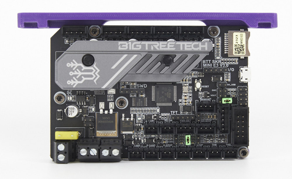
The jumpers used in the photo are green for illustrative purposes only. Remove any jumpers not shown in the photo.
¶ The Raspberry Pi
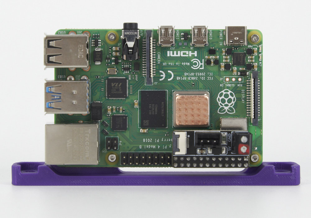
Let's prepare the Raspberry Pi as well:
- Print the Raspberry Pi bracket. Install the Raspberry Pi onto the bracket using M2x10 self tapping screws.
- Remove the adhesive backing on the copper heatsink and apply it to the main processor on the Raspberry Pi.
- Install the Pi Adapter PCB onto the GPIO header of your Raspberry Pi. We will use this to supply 5V power to the Pi.
¶ The DC Power Supplies
¶ 5V DC Power Supply
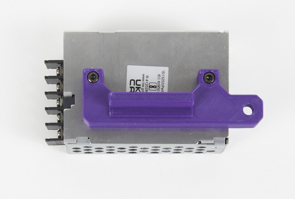
To save space, we've designed a printed bracket that mounts the 5V power supply sideways, print this part here.
¶ 24V Power Supply (EU)
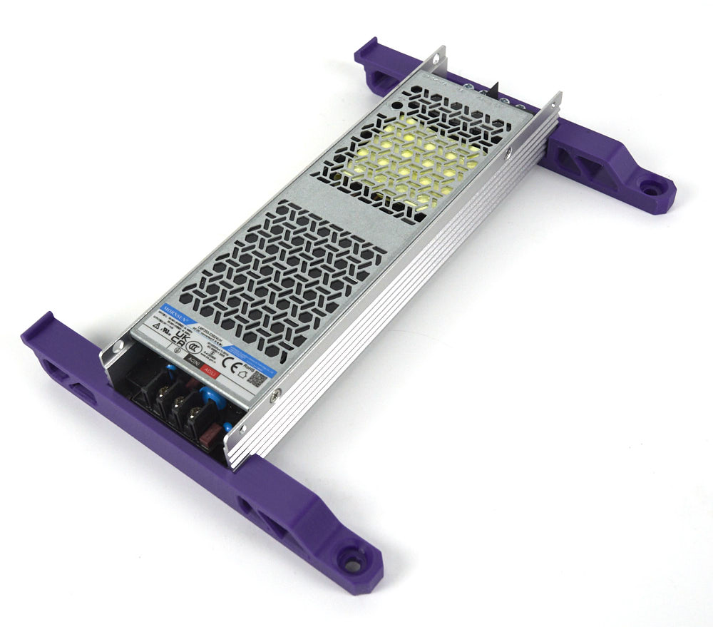
If you are received your kit from an EU reseller, you will likely receive the LMF350-23B24UH slim power supply. Print the mounting bracket here. Use four M3x8 SHCS screws to mount the power supply to the brackets from the bottom side.
¶ 24V Power Supply (non-EU)
If you received the LM350-10B24 Power supply, print the normal mounting brackets.
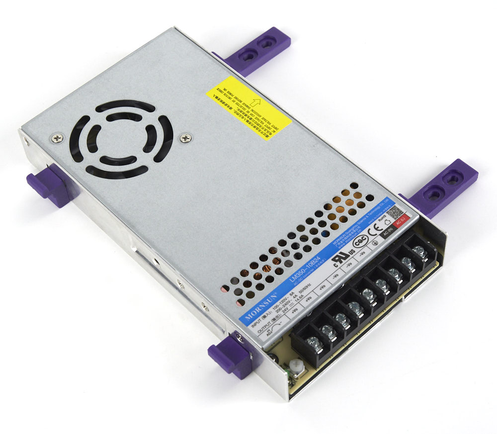
Remember to set the input voltage switch appropriate to your regional mains voltage. (115V for North America)

¶ WAGO Terminals
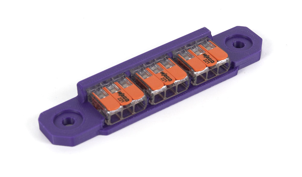
WAGO terminals are provided in this kit to help with mains voltage wiring. print the mount here. The WAGO terminals are simply snapped into the printed part.
¶ USB Adapter PCB
Print the mounting bracket for the USB adapter PCB here.
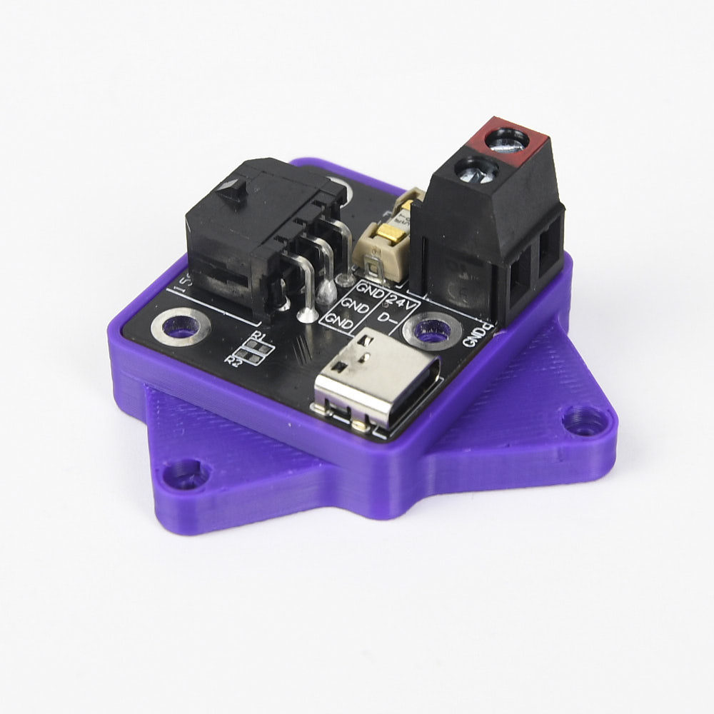
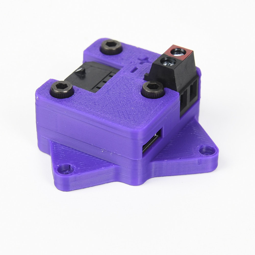
A printed cover is also available here. Use three M3x10 SHCS screws to install the cover onto the base - the screws thread directly into the plastic.
¶ The AC Inlet
Your kit should include a pre-wired AC inlet. Double check that the wiring correct, the final layout should be as follows:
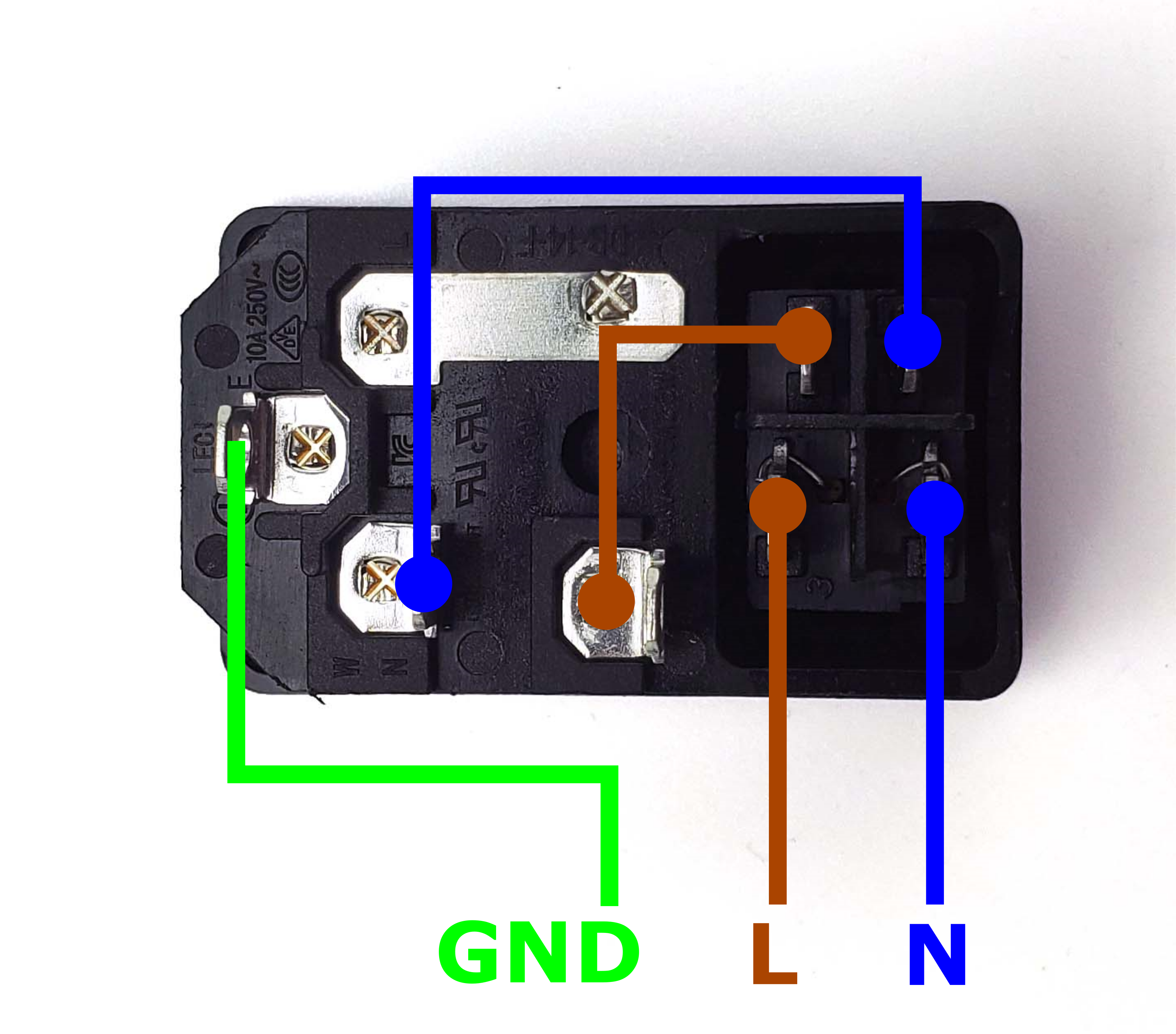
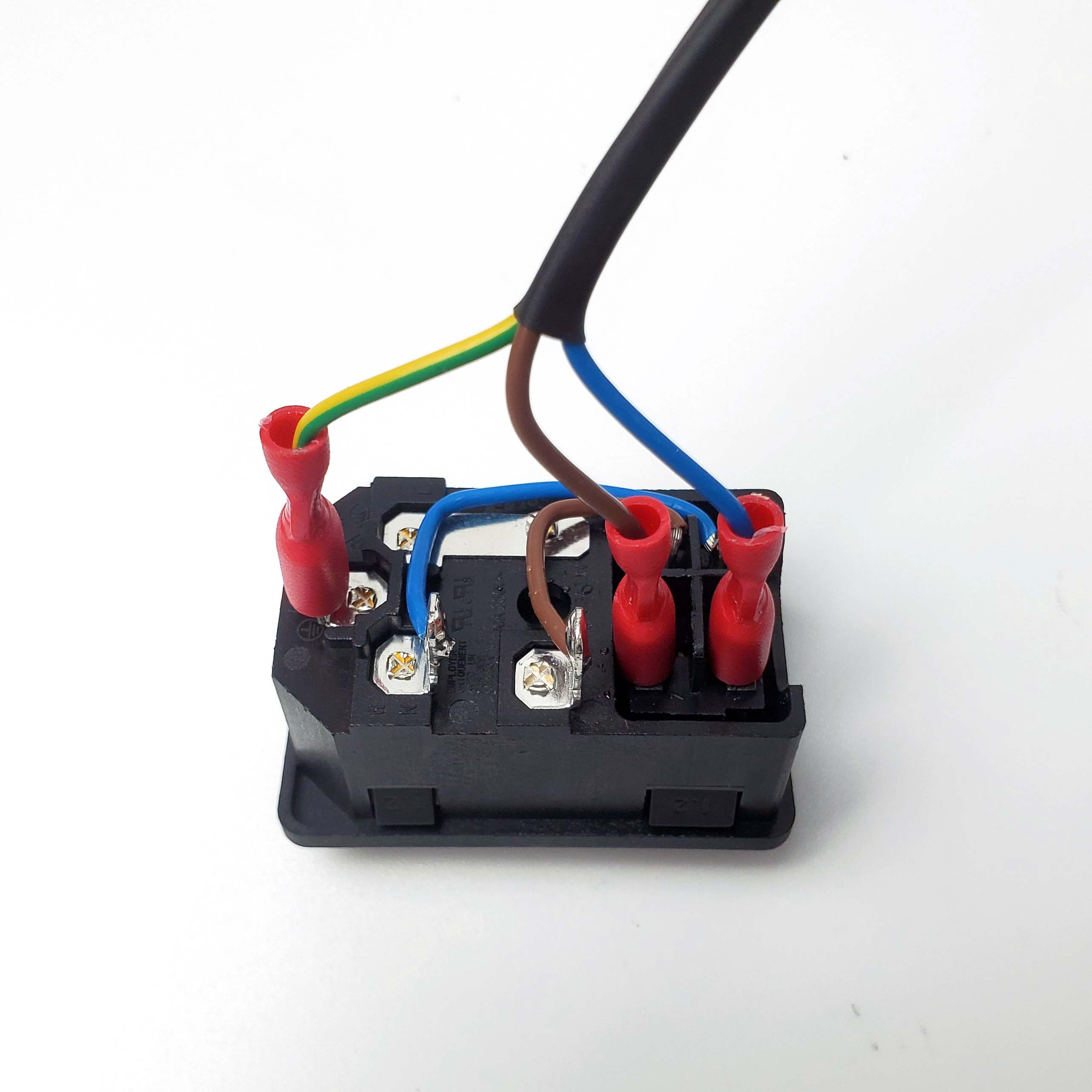
Take the inlet cable included in the kit and attach the wires using the above layout as reference. When wired correctly, your live wire will be protected by a fuse, and the switch on the front side of the inlet will operate correctly (lights up when turned on).
¶ Below Deck Wiring
¶ Placement of the Electronics
- Follow the Voron manual for placement locations of the SKR mini, power supplies, and Raspberry Pi.
- Cut the provided PVC wiring duct into two segments: a long segment that is the same width as the horizontal beams; and a remaining segment to place beside the SKR mini.
- Use VHB tape to mount the USB adapter between the SKR mini and 5V power supply.
- Mount the 3x3 Wago Terminal across from the 24V power supply. Use two M5x10 screws for mounting.
The final result should look like the following picture:
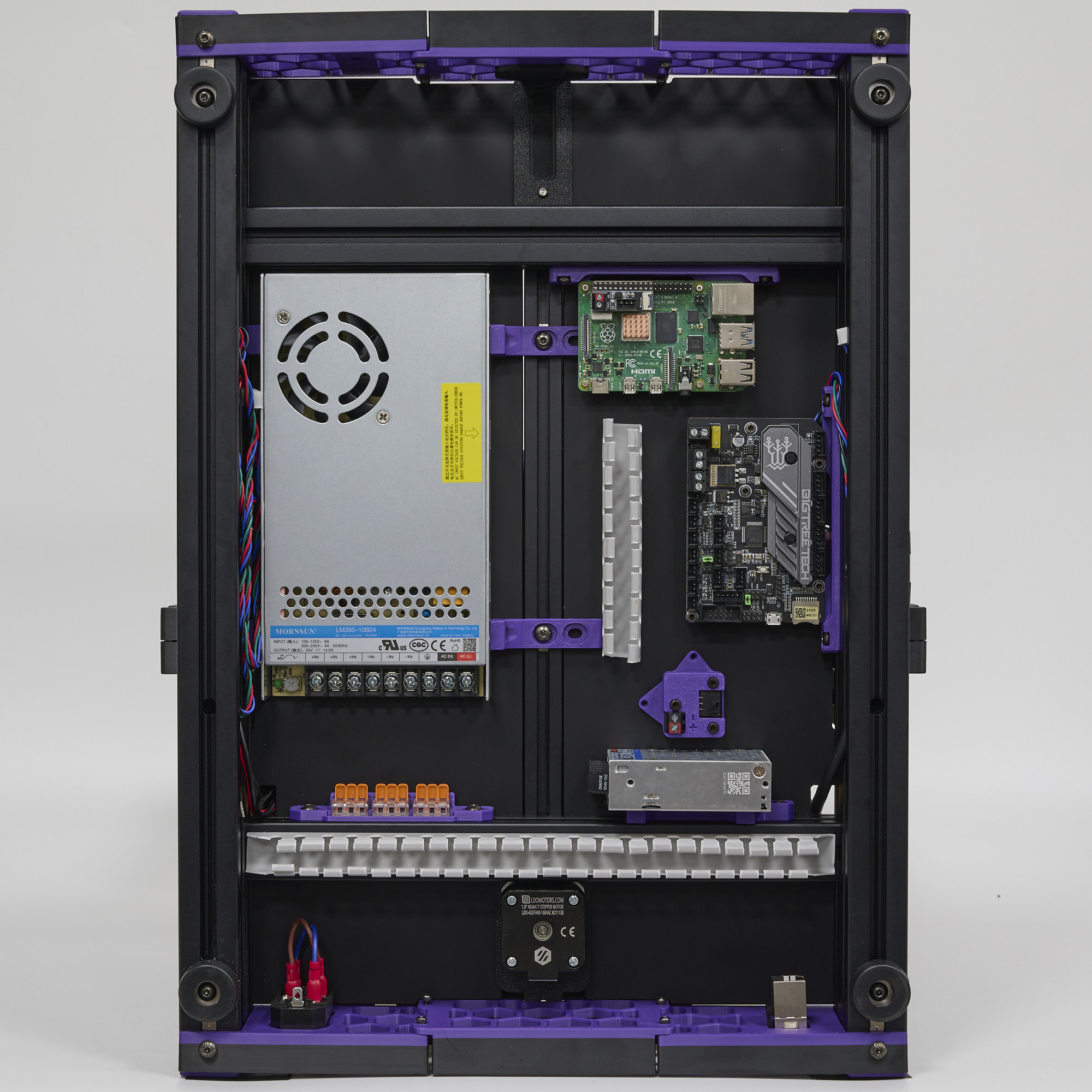
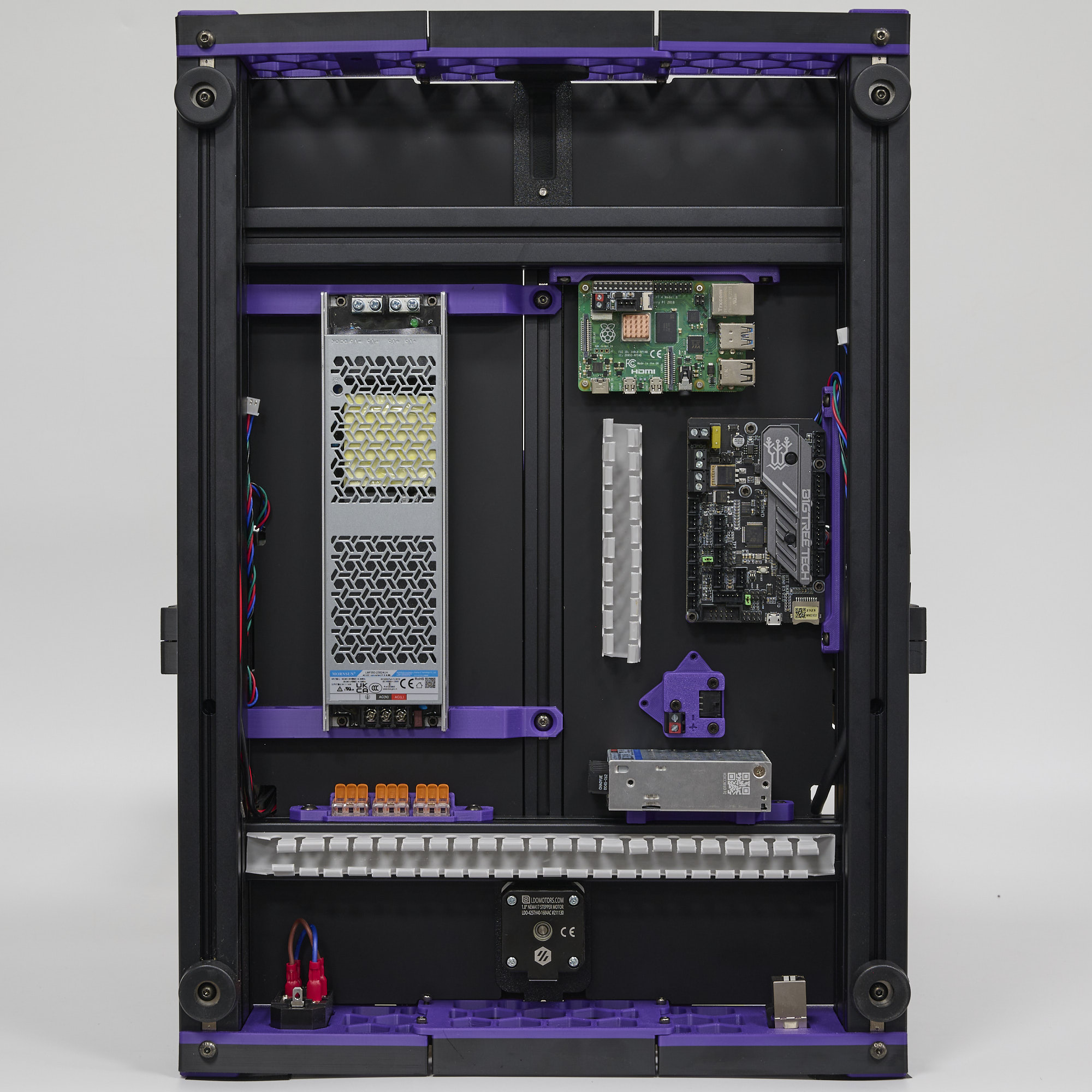
For EU users, the power supply is mounted in approximately the same location, the rest of the guide will use the US PSU for illustration.
¶ Power Connections
¶ Connecting Mains
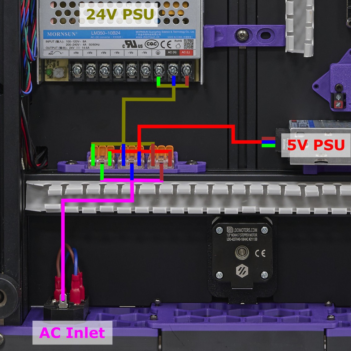
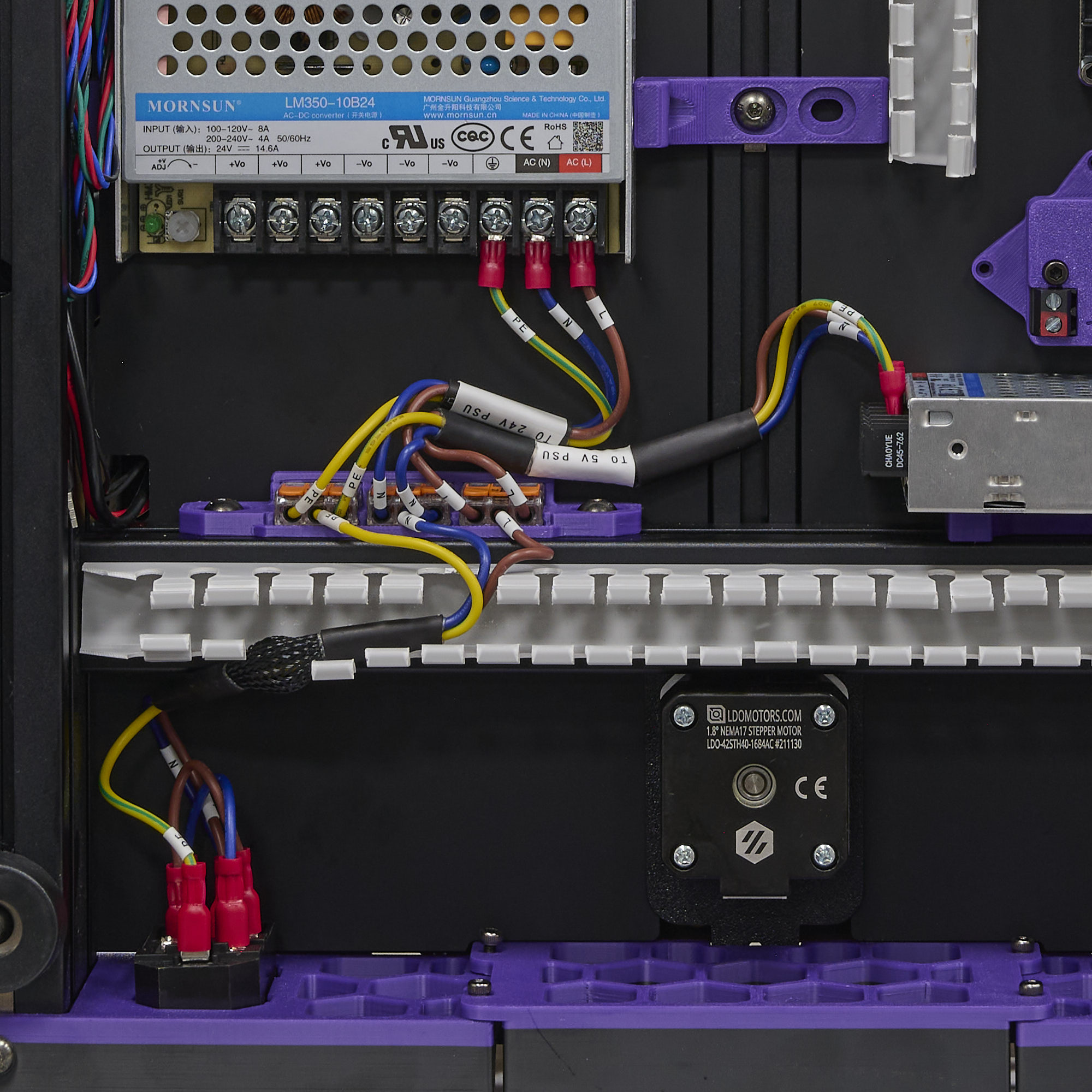
Let's connect the AC mains wires. Connect each of the live (L, brown), neutral (N, blue), earth (GND, yellow/green) ends of the AC inlet cable to a seperate WAGO terminal. Then connect the respective live, neutral, earth ends of the PSU cables from the WAGO terminals to the 24V and 5V power supplies. Make sure that the inlet cable is attached to the AC inlet before instaling it to the machine (doing so afterwards can be very difficult)! Refer to the following diagram:
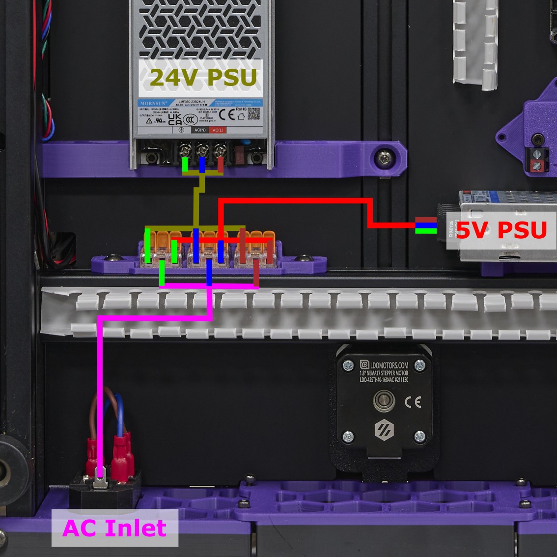
Users that received the slim LMF350-23B24UH power supply can refer to this diagram below:
Double check, then triple check the connections. An incorrect connection will very likely damage or destroy your components. The final connection looks like this:
¶ DC power
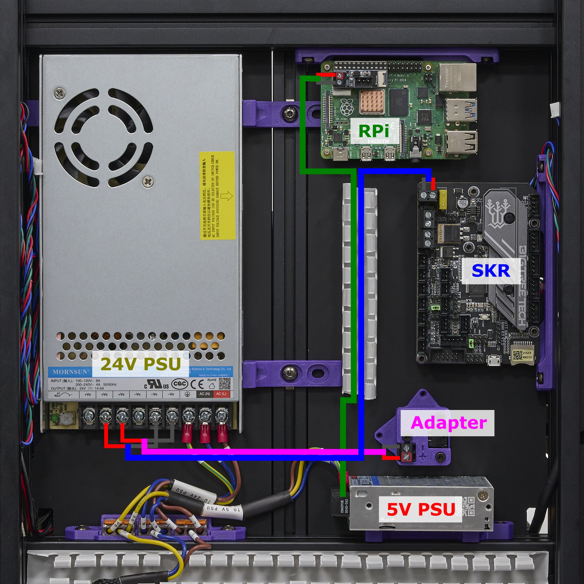
Double check all the mains connections and try powering up the power supplies. If everything is correct, the LEDs on both power supplies should turn on. Now we can wire up the DC power to the controller board and Raspberry Pi. Refer to the diagram below:
Users that received the slim LMF350-23B24UH power supply can refer to this diagram below:
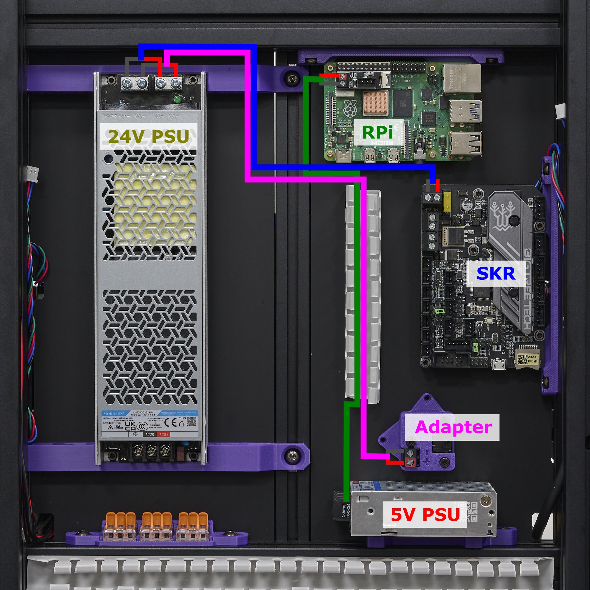
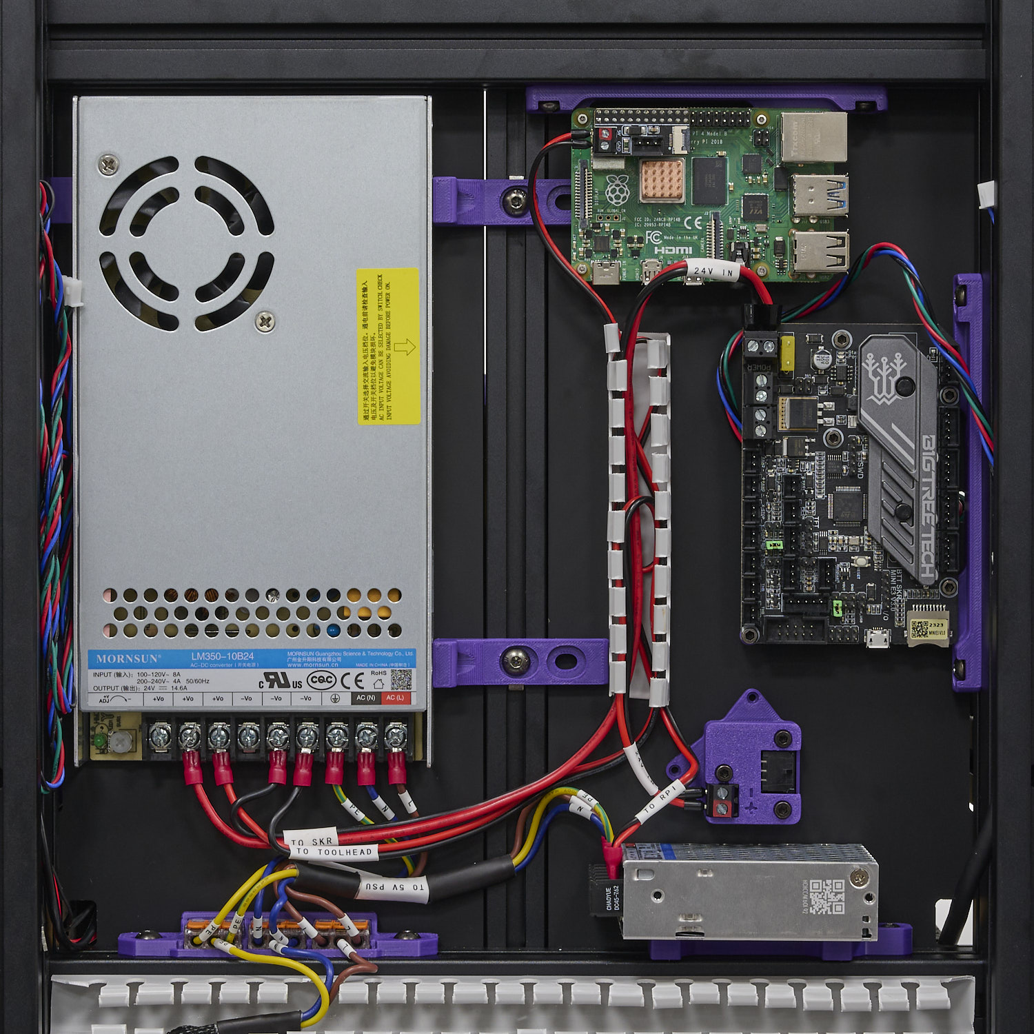
Pay careful attention to the polarity of all the connections! Beware that inverting the 24V power can destroy your controller board! The final result should look like this:
¶ Checking the power connections
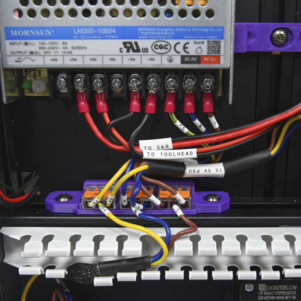
Before we proceed to the rest of the guide, lets check all the connections we've made so far. Check the follow picture for what the connection at the WAGO terminals look like.
- Make sure only wires of the same colour are connected to the same terminal.
- At the same time let's check the connections made on the 24V power supply.
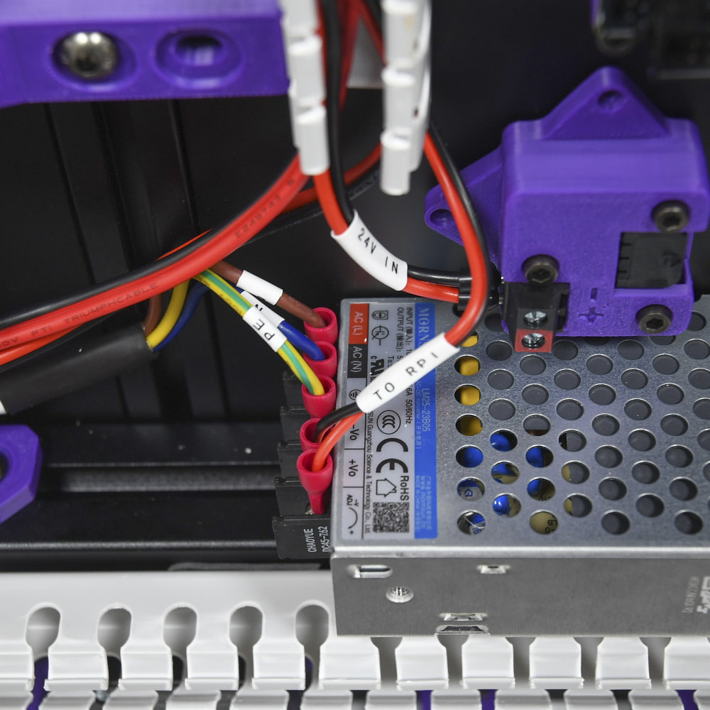
Next lets check the connections made at the 5V power supply and USB Adapter. Pay close attention to the polarity of the screw terminals.
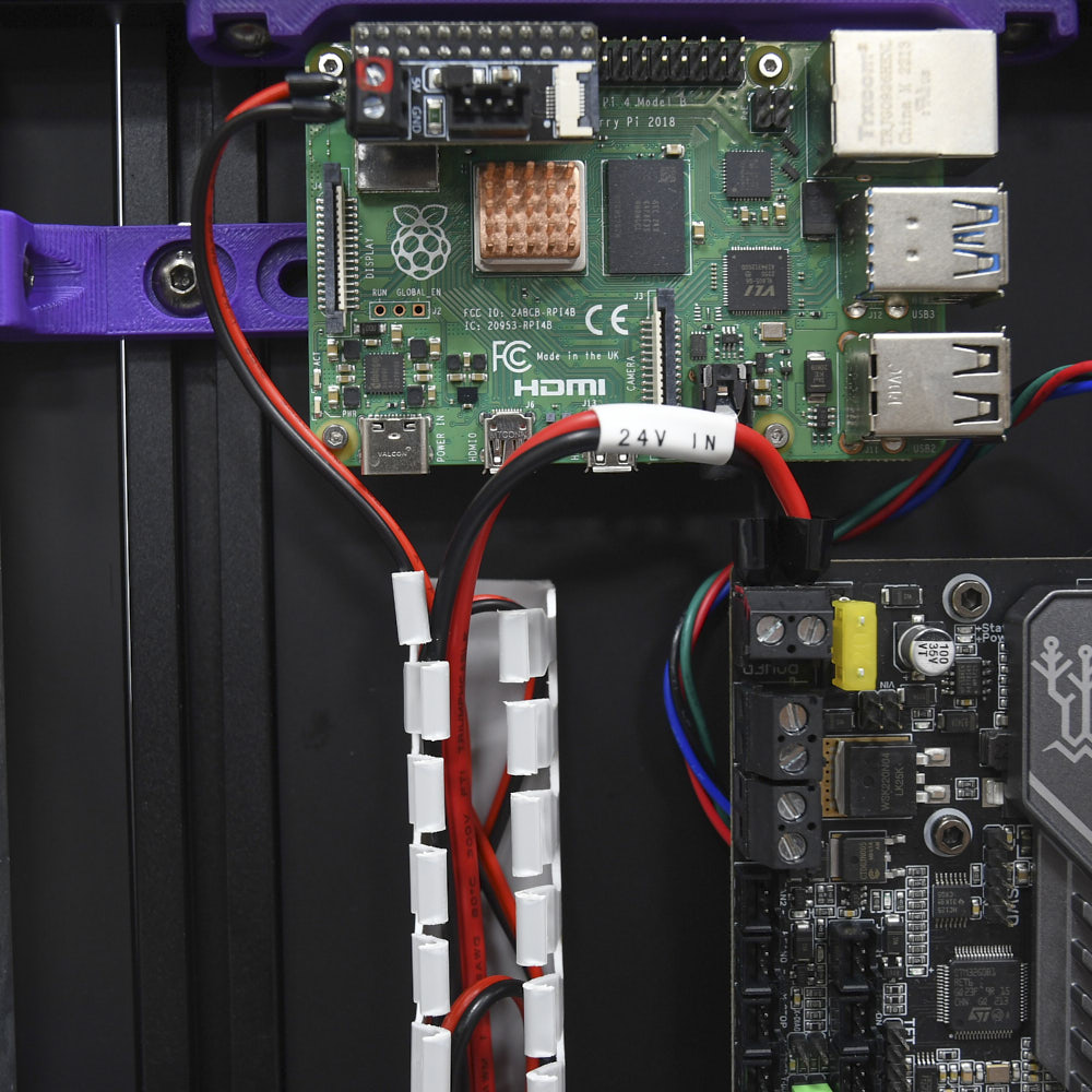
Finally, lets check the connections made at the Raspberry Pi and SKR mini mainboard. Once again, pay close attention to the polarity of the screw terminals.
¶ Heated Bed & Fan Connections
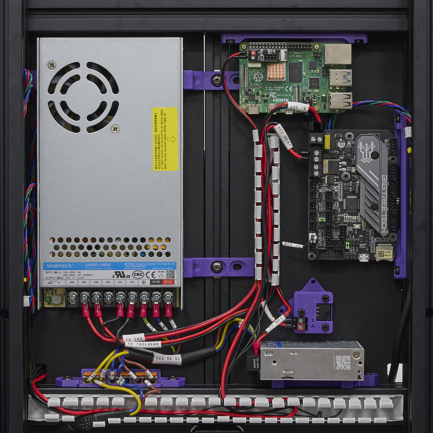
In this step, we will connect the heatbed and controller fan to the controller.
- Connect the black and white cable labelled BED TH to the THB connector on the SKR
- Connect the black and red cable labelled BED HEAT to HB screw terminal. Check this pinout diagram to ensure you are plugging in the correct screw terminal.
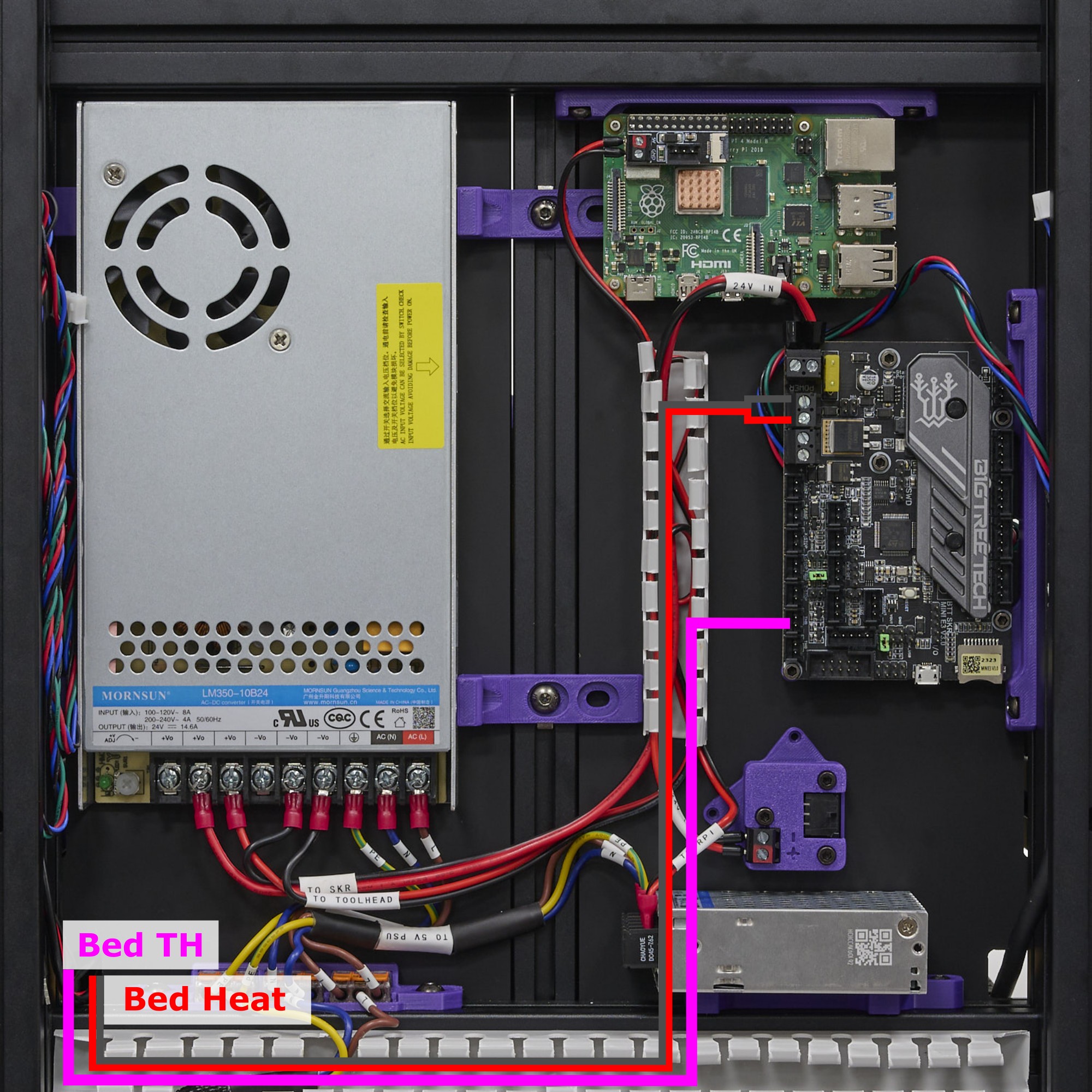
The final result looks like this:
¶ Connecting the X/Y/Z Stepper Motors
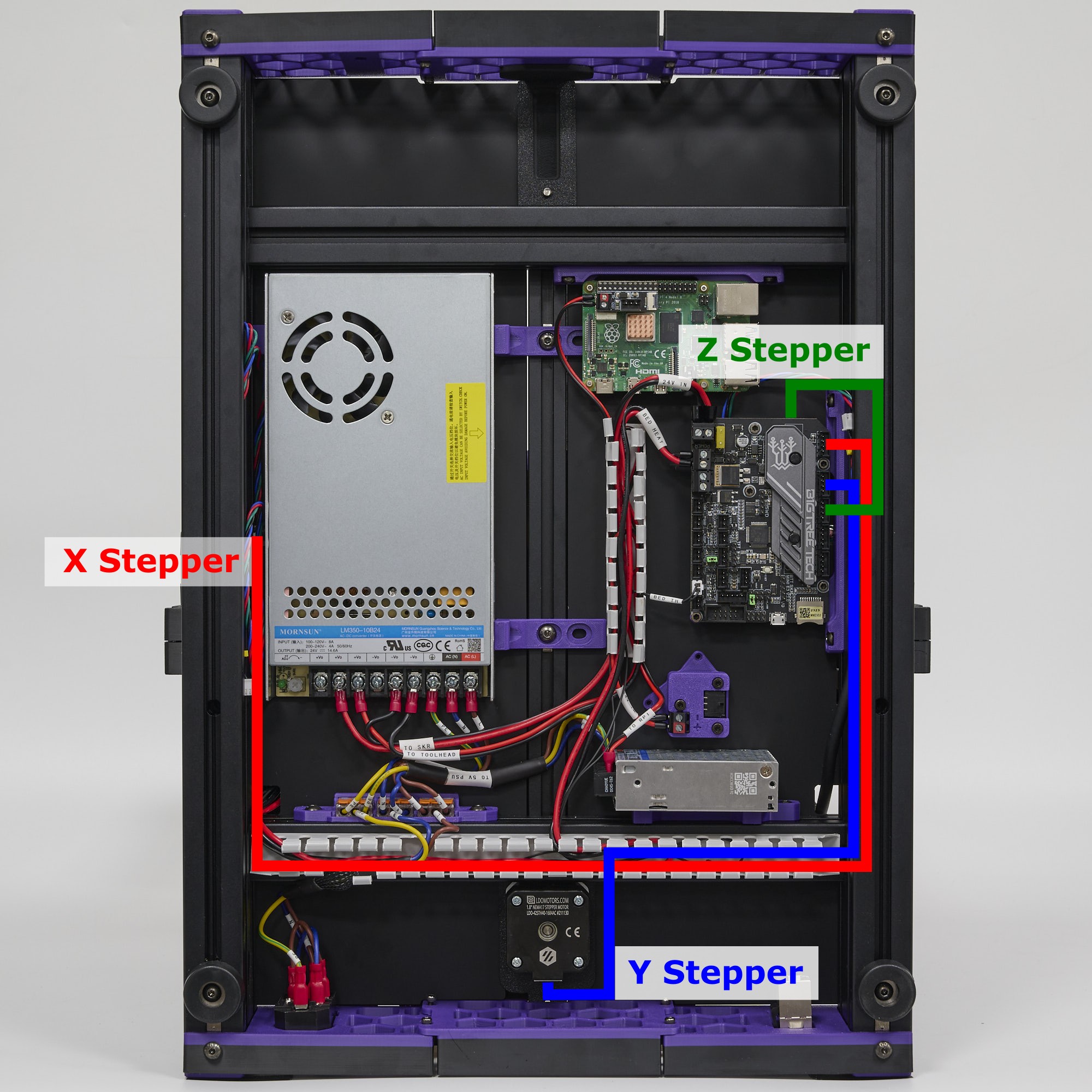
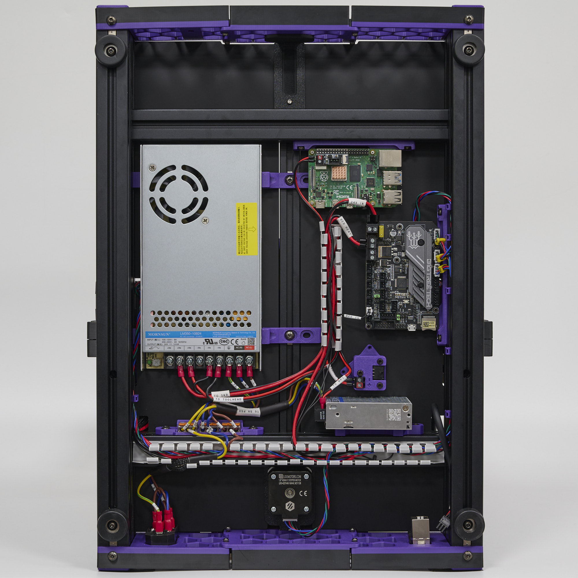
In this step, we will connect the X, Y and Z Stepper Motors. The Z Stepper wires are routed from underneath the controller board. Note that the aluminium extrusions can be used as built-in wire ducts - simply tuck the cables into the slots of the extrusions. Finally, printed wire clips can be used to prevent the cables from dangling out of the extrusion slot. Refer to the following diagram:
The final result should look like this:
¶ USB Connections
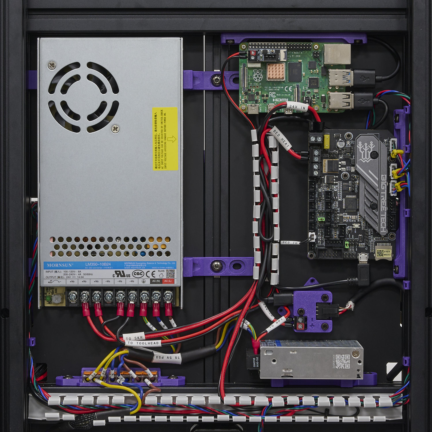
In this step, we make all the USB connections:
- Use the angled micro USB cable to connect the SKR mini to the Raspberry Pi
- Use the USB C to USB A cable to connect the USB Adapter to the Raspberry Pi
- Connect the Toolhead Cable to the Microfit port on the USB adapter.
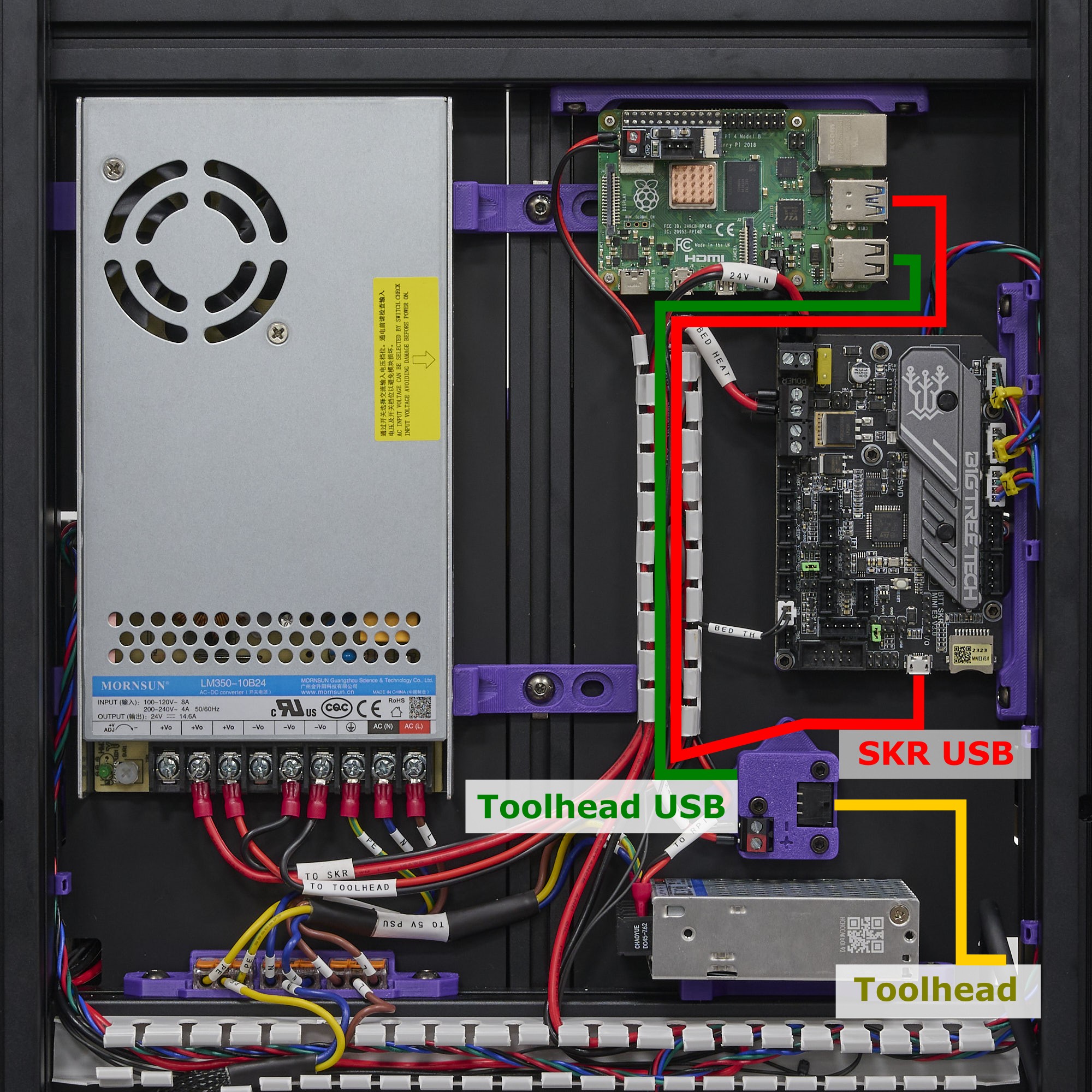
The final result:
¶ Connecting the LCD, PCB Fan, and LED Cable
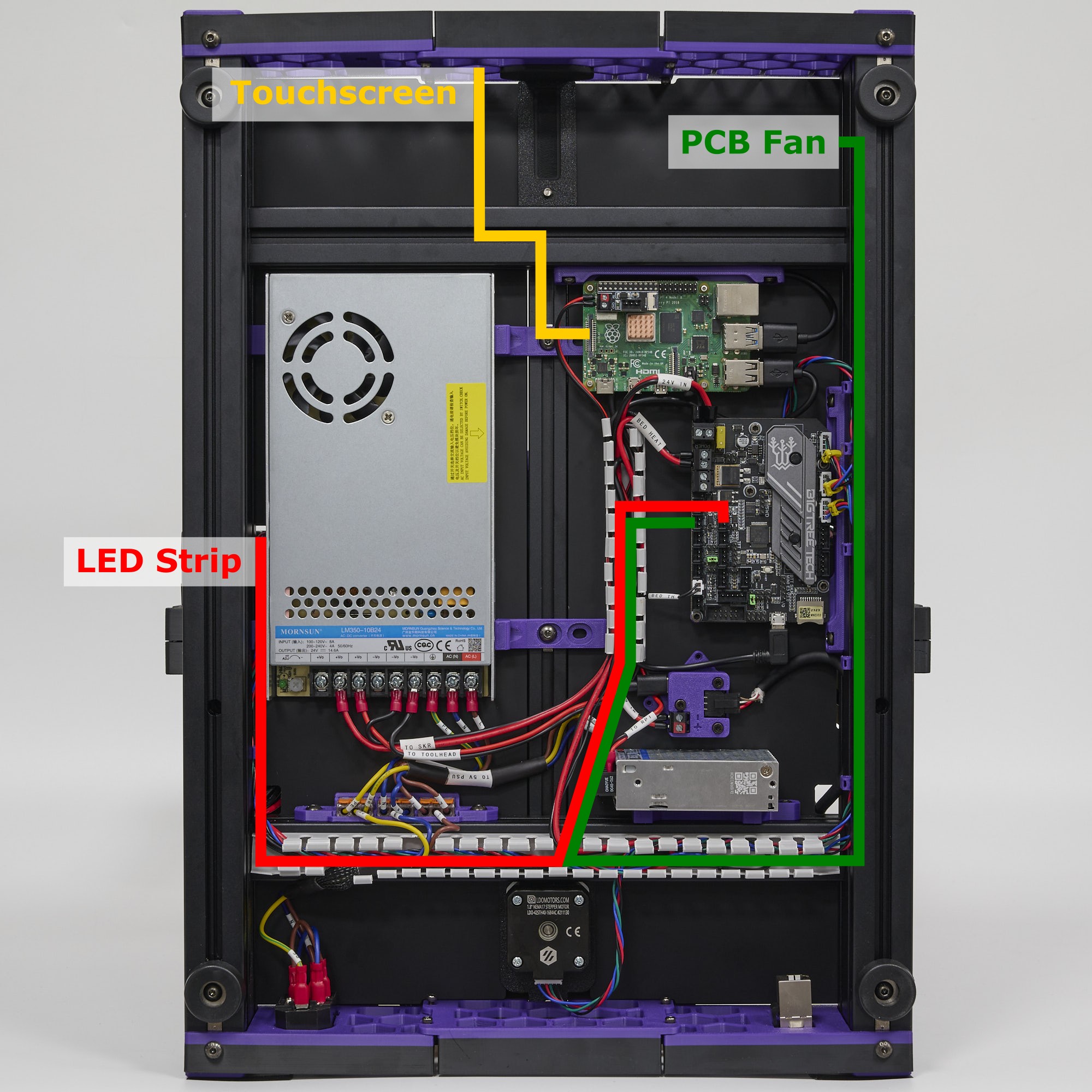
In this step, we will connect the LCD panel and the LED strip cable.
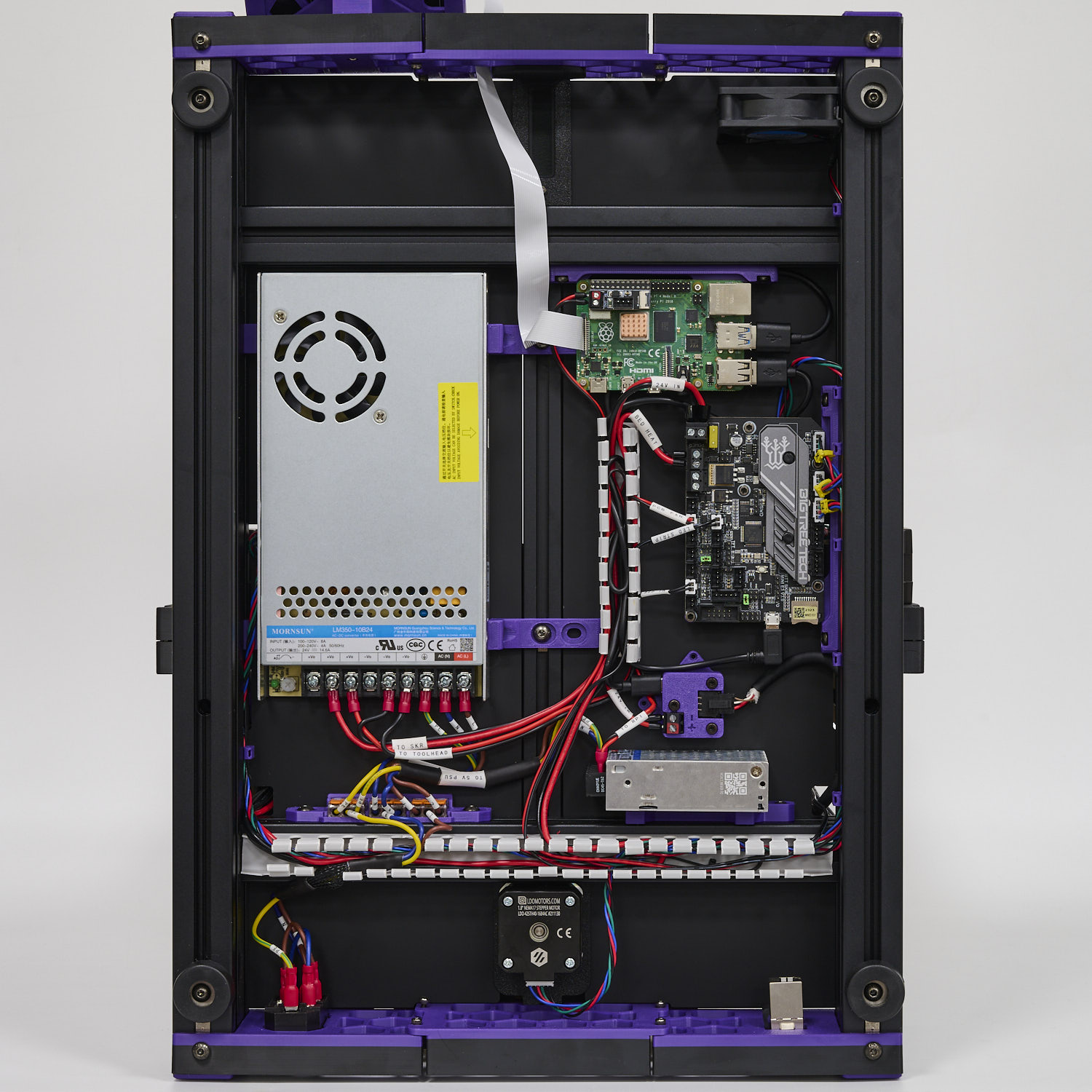
- Use the provided FFC ribbon cable (30cm length) to make the connection between the touch panel LCD and Raspberry Pi. Both sides of the FFC cable are the same, but pay careful attention to the orientation when seating it into the LCD and RPI. Double check your connection and read about setting up the touchscreen in this guide.
- Use VHB tape to install the 6020 fan in the location shown in the photo below. Plug the fan cable into the FAN0 port of the SKR mini mainboard. As with the stepper motor cables, the fan cable can be tucked into the extrusion slot for neater cable management.
- Route the LED cable through the same hole as the X stepper cable and install it into the FAN1 port of the SKR mini mainboard.
The final result:
¶ Final Touch-ups
With all the connections completed, we can now cover the wire ducts and tie-up any exposed bundles of wire.
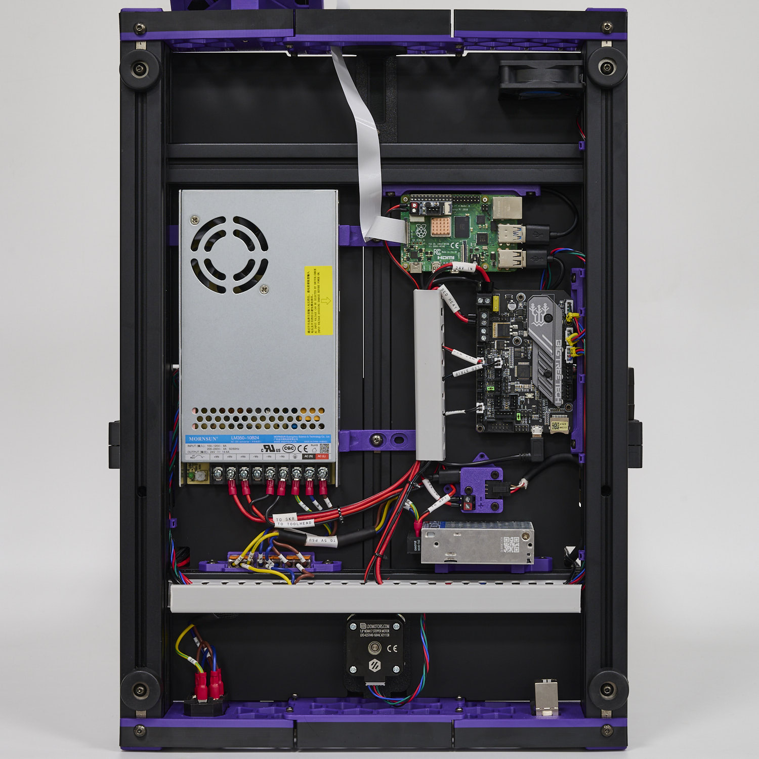
Congratulations! You have now finished wiring your Switchwire!
¶ Software Setup
Now that you have completed hardware wiring, it is time to move on to software setup. The following sections outline resources you can use to finish setting up software for your printer. Many of the instructions below are derived from the official Voron documentation site which you can visit here.
¶ Raspberry Pi OS Setup
We first need to install an operating system onto your Raspberry Pi. The easiest way to do this is to use their official imager.
- Download and run the Raspberry Pi Imager.
- Under Advanced options, enable SSH, set a username and password, and enter your WIFI info.
- Under Operating System Choose Raspberry Pi OS (other) -> Raspberry Pi OS Lite (32bit)).
- Insert the SD card provided in the kit and choose it under storage. Click Write and wait for the Imager to finish writing the data into the SD card.
- Remove the SD card from your computer and insert it into the Raspberry Pi
¶ Remotely Accessing Your Raspberry Pi via SSH
Many of the following steps below require you to remotely run commands on your Raspberry Pi via SSH. If you are on Windows, putty is the goto tool. If you are on Mac OS, you can simply run ssh on your Terminal. For more info about remotely accessing your Raspberry Pi using SSH, read this article.
¶ Klipper and Web Interface Setup
On your Raspberry Pi, you will need to install Raspberry Pi OS Lite, Klipper, and a web interface to manage your printer. The most popular options for a web interface are Fluidd and Mainsail - both are great options with similar controls, you can't go wrong picking either of them. To make installation a breeze, we recommend using KIAUH, which is a script that helps you install Klipper, Fluidd/Mainsail and any other dependancies that may be required.
- Follow the instructions on the KIAUH github page.
- Use KIAUH to install Klipper, then Moonraker, then Fluidd or Mainsail, then KlipperScreen.
¶ Setting up the Touch Screen
If you followed the previous step with KIAUH, then KlipperScreen should be successfully installed. Read this guide for information on touchscreen setup and instructions for rotating screen orientation.
¶ Mainboard Firmware Setup
Next, you need to install Klipper firmware onto your SKR mini e3 V3.0 mainboard - this allows the main Klipper software on your Raspberry Pi to talk to and control your mainboard.
- Follow the instructions on the Voron docs site to install Klipper Firmware to the SKR.
- Run
ls /dev/serial/by-id/on your Raspberry Pi using SSH. You should see a string of text likeusb-Klipper_stm32fG0_12345678900DB0D8-if00. This is the MCU path for the SKR, copy it for later use.
¶ Klipper Configuration
With software and firmware both successfully installed. We can now move on to adding Klipper configuration files. These configuration files basically tell Klipper how our printer is wired. It also contains other useful data such as custom macros, tuning values, and so on.
- Open your printer's web interface by entering your Raspberry Pi's IP address in any browser. Initially, you will see an error message indicating a missing “printer.cfg” file.
- If you followed our wiring guide, you can use our pre-made configuration file. Download the configuration file and upload it via the Mainsail/Fluidd web interface. In Mainsail, go to Machine (Wrench icon). In Fluidd, goto Configuration ( {…} icon ). Both web interfaces allow you to upload by directly drag and drop the files onto the their webpage. Rename the configuration file to
printer.cfg. - Edit the printer.cfg file, under the
[mcu]section, replace{REPLACE WITH YOUR SERIAL}with the SKR MCU path you obtained in the previous steps.
¶ Initial Printer Setup and Tuning
With all the configuration files in place, you should now be able to use Fluidd/Mainsail to perform basic controls on your 3D printer. However, there are still a few more stepss you should follow before starting your first print. Follow the initial startup guide on the Voron documentation site.