The LDO toolhead wiring kit is a three part system designed to simpify wiring of Voron toolheads (afterburner and stealthburner). It is composed of the toolhead PCB, toolhead cable, and breakout PCB. The circuit drawings and CAD files for the PCBs can be found here.
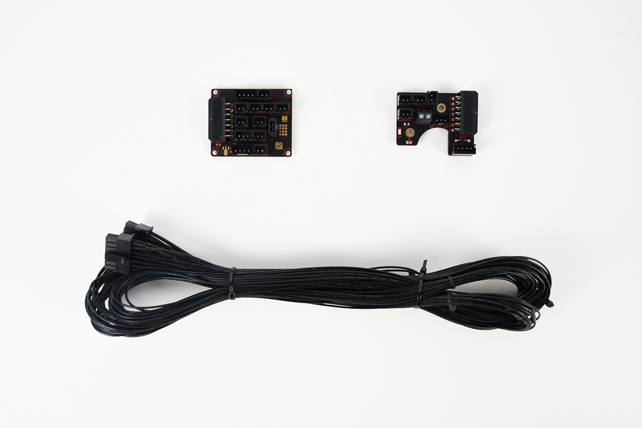
¶ The Toolhead PCB (Afterburner Version)
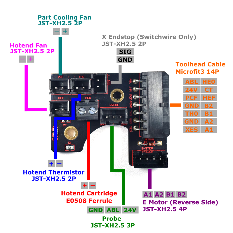
The toolhead PCB is based on hartk's toolhead PCB design. The main purpose of the toolhead PCB is to combine all the signals and wires (e.g. thermistors, fans, hotend) on the toolhead PCB into a single cable. Compared to the orignal hartk design, the LDO PCB has a few minor differences:
- The hotend cartridge connector is screw terminal instead of a microfit 3 connector.
- The onboard thermistors use NTC10K thermistor, more info here.
Apart from the above mentioned differences our PCB has the same shape and mounting hole positions, and the 14 pin microfit pinout is 100% compatible with the original hartk PCB.
¶ Pinout
The table below briefly describes the purpose of each port located on the toolhead PCB.
| PCB Label | Name | Connector | Description |
| HEF | Hotend Fan* | JST-XH-2P | Fan port for cooling the hotend heatsink. Note that only 24V fans are compatible |
| PCF | Part Cooling Fan* | JST-XH-2P | Port for part cooling fan. Note that only 24V fans are compatible |
| HE0 | Hotend Heater* | E0508 Ferrule | Port for hotend heater cartridge. |
| TH0 | Hotend Thermistor | JST-XH-2P | Thermistor port for hotend |
| XES | X Endstop | JST-XH-2P | X endstop port. Only used in Switchwire builds, unused in V2 and Trident. |
| PROBE | Probe | JST-XH-3P | Probe port. Accepts 24V inductive probes, also compatible with klicky probes. |
| E-STEP | E Stepper Motor | JST-XH-4P | Extruder stepper motor port |
| Toolhead Cable | Microfit3-14P | This port connects to the 14pin toolhead cable. |
*Note that the hotend fan, part fan, and hotend heater all share the same 24V rail on their positive terminals, PWM switching is controlled by their respective negative terminals.
¶ The Toolhead PCB (Stealthburner Version)
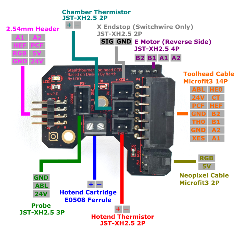
Starting from Rev. C, our Voron2.4 and Trident kits will ship with the Stealthburner PCB. The Stealthburner PCB is based on hartk's two piece toolhead PCB design. The design consists of:
- The main toolhead PCB - which installs into the wiring enclose in the side of the Clockwork 2 extruder.
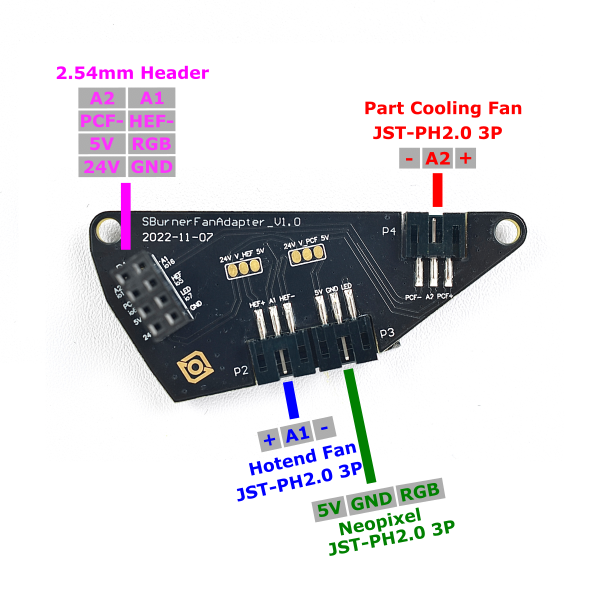
- The fan adapter PCB - which installs onto the back of the 5015 fan in the Stealthburner main body.
While the LDO stealthburner PCB uses the same PCB outline as the hartk's design, it uses a different circuit design. The LDO version is designed to be completely compatible with the original LDO breakout PCB (see below) while requiring only a small number of cable modifications for those upgrading from the old LDO afterburner PCB.
¶ Pinout: Main Toolhead PCB
The table below briefly describes the purpose of each port located on the toolhead PCB.
| PCB Label | Name | Connector | Description |
| HE0 | Hotend Heater | E0508 Ferrule | Port for hotend heater cartridge. |
| TH0 | Hotend Thermistor | JST-XH-2P | Thermistor port for hotend |
| XES | X Endstop | JST-XH-2P | X endstop port. Only used in Switchwire builds, unused in V2 and Trident. |
| PROBE | Probe | JST-XH-3P | Probe port. Accepts 24V inductive probes, also compatible with klicky probes. |
| E-STEP | E Stepper Motor | JST-XH-4P | Extruder stepper motor port |
| CT | Chamber Thermistor | JST-XH-2P | Connects to an external thermistor for more accurate chamber temperature readings. |
| Fan Adapter Header | 2x8 M-Header | Plugs into the female header on the Fan Adapter PCB | |
| Toolhead Cable | Microfit3-14P | This port connects to the 14pin toolhead cable. | |
| Neopixel Cable | Microfit3-2P | This port connects to the 2pin neopixel cable. |
¶ Pinout: Fan Adapter PCB
The table below briefly describes the purpose of each port located on the toolhead PCB.
| PCB Label | Name | Connector | Description |
| HEF+/A1/HEF- | Hotend Fan* | JST-PH-3P | Fan port for cooling the hotend heatsink. 24V/5V selectable, defaults to 24V. |
| PCF+/A2/PCF- | Part Cooling Fan* | JST-PH-3P | Port for part cooling fan. 24V/5V selectable, defaults to 24V. |
| 5V/GND/LED | Neopixel | JST-PH-3P | For connecting to the neopixel chain on the stealthburner. |
| Toolhead Cable | 2x8 F-Header | Plugs into the male header on the main toolhead PCB |
*The hotend fan and part fan can be independently changed to 5V in two steps:
- Severe the 24V connection by cutting the trace between the 24V pad and V_HEF/V_PCF pad
- Make a soldered bridge connection between the 5V pad and V_HEF/V_PCF pad
¶ The Toolhead Cable
The toolhead cable is a cable designed to be carried through the gantry cable chains within Voron printers. All individual wires within the cable are UL1332 high strand count cables. UL1332 wires have durable FEP insulation to reduce friction between the wires and cable chain. The high strand count helps prevent breakage with repeated bending cycles.
Caution! The zipties that come with the cable must be removed prior to installation into the cable chains. These zipties are used to prevent tangling during shipping, however, they can get caught within the cable chain and can cause damage if not removed.
¶ The Breakout PCB
The breakout PCB serves the opposite purpose of the toolhead PCB - it breaks out the 14pin toolhead cable into individual ports that can then be connected to the mainboard. The breakout PCB have ports that correspond to their counterparts in the toolhead PCB. The breakout PCB also accepts the 4 pin endstop cable included in LDO kits.
¶ Pinout
The table below briefly describes the purpose of each port located on the breakout PCB.
| PCB Label | Name | Connector | Description |
| HEF/24V | Hotend Fan* | JST-XH-2P | Fan port for cooling the hotend heatsink. HEF denotes the negative pin. |
| PCF/24V | Part Cooling Fan* | JST-XH-2P | Port for part cooling fan. PCF denotes the negative pin. |
| HE0/24V | Hotend Heater* | Microfit3-2P | Port for hotend heater cartridge. HE0 denotes the negative pin. |
| TH0/GND | Hotend Thermistor | JST-XH-2P | Thermistor port for hotend. TH0 denotes the signal pin. |
| CT/GND | Chamber Thermistor | JST-XH-2P | Thermistor port for the onboard thermistor on the toolhead PCB. CT denotes the signal pin. |
| XES/GND | X Endstop | JST-XH-2P | X endstop port. XES denotes the signal pin |
| YES/GND | Y Endstop | JST-XH-2P | Y endstop port. YES denotes the signal pin |
| Vin/X/Y/GND | Input for the Endstop PCB | JST-XH-4P | The input port from the endstop PCB used in V2.4 or Trident. If a hall endstop PCB is used, extra circuit on the PCB needs to be populated to generate 5V at Vin. This port is not used in Switchwire builds. |
| 24V/ABL/GND | Probe | JST-XH-3P | Probe port. |
| E-MOTOR | E Stepper Motor | JST-XH-4P | Extruder stepper motor port |
| CFAN/24V | Chamber Fan** | JST-XH-2P | Connects to the electronics chamber fan in the switchwire. CFAN denotes the negative pin. |
| LED/24V | LED** | JST-XH-2P | Connects to the LED strip in the switchwire. LED denotes the negative pin. |
| CFAN/LED | Chamber Fan + LED Control Signal** | JST-XH-2P | Connects to the LED/CFAN control signals on the mainboard. Only used in Switchwire. |
*Caution! Note that polarity matters when making connections between the breakout PCB and your mainboard. Incorrect polarity can cause a short circuit and destroy your mainboard! The hotend fan, part fan, and hotend heater all share the same
**Only used in Switchwire builds.
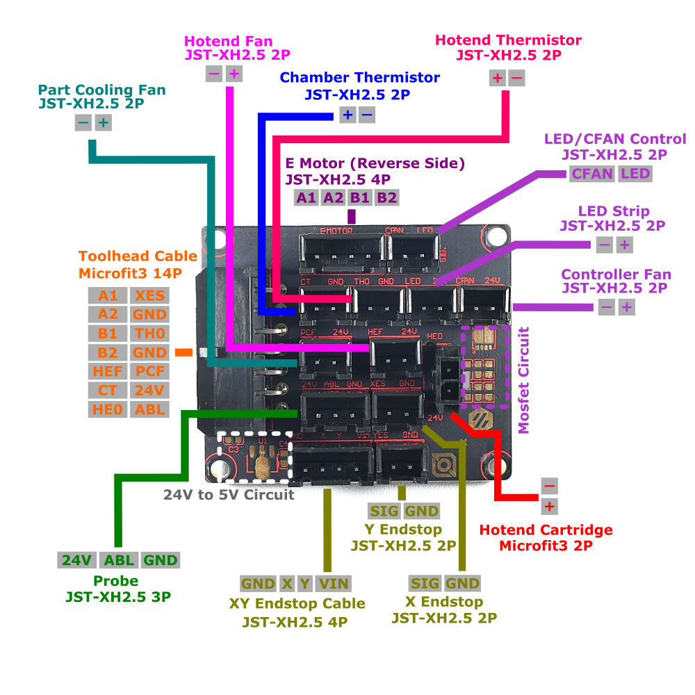
¶ Unpopulated Circuitry on the Breakout PCB
The breakout PCB contains two circuits that may or may not be populated:
- Mosfet circuit for CFAN/LED. This circuit is only populated for breakout boards supplied in Switchwire kits.
- 5V power supply circuit. This circuit generates a small 5V supply the Vin pin for those that wish to use the Hall Endstop PCB. If you wish to solder this circuit yourself, check the circuit below. Note that this circuit is not designed for high current loads and should only be used to power the hall endstop PCB.
| Breakout Board 5V circuit | ||
| Ref | Item | Form Factor |
| U1 | 7805 Voltage Regulator | SOT-89 |
| C3 | 330NF, 50V Capacitor | 0603 |
| C4 | 100NF, 50V Capacitor | 0603 |