This guide contains directions for wiring a Rev. D LDO Voron Trident Kit using the pre-cut, pre-terminated cables included in the LDO kit. Important! Mains wiring should only be performed by certified personnel trained in local regulations and safety standards. If at any point you find the images in this guide to be too small, you can check out the source images from this github location.
¶ Tools
Here is a short list of tools you should prepare:
- 2.5mm slot head screwdriver (included in kit), This screwdriver is used to manipulate the plug type terminals.
- PH2 Phillips screwdriver (not included in kit), This screwdriver is used on the power supply and SSR.
- Multimeter (not included in kit), Used to check connectivity.
¶ Pre-Wired Items
The following items should have pre-cut lengths, labels, and crimped connectors:
- Heatpad, joined with thermal fuse and installed on bed.
- Hotend Thermistor
- Hotend Cartridge
- Hotend Fan
- Print Cooling Fan
- Z Probe
- Electrical Chamber Cooling Fan
- Filter Fan
- Toolhead PCB cable
Certain stepper motor cables are purposely left longer than needed for people with different setups. You may choose to cut them or leave them as is during wiring.
¶ Above Deck Wiring
¶ Insulating the Z Probe
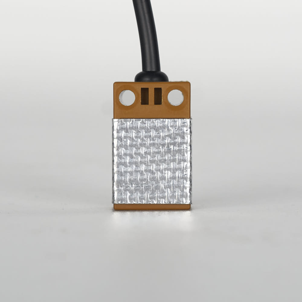
Our kit comes with a small strip of fiber glass tape. This tape is used to help insulate the Z probe from radiative heat from the the hotend. We recommend covering the front and sides of the probe with at least 2 layers of this tape. Do not cover the back or the bottom of the probe, if you have problems triggering the probe, try removing bits of the tape as it may be interfering with probe sensing. Optional: consider cutting an opening in the tape, around the LED of the Z probe - this will allow you to see the LED light up when the Z probe is triggered.
¶ Wiring the Toolhead PCB
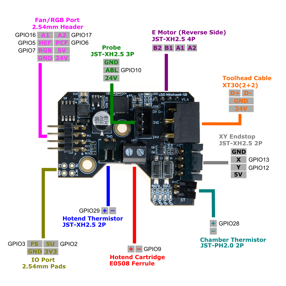
The Rev. D kit contains parts to build the Stealthburner + Clockwork 2 toolhead. For more information on these PCBs, refer to the wiring kit page and github repository.
The main toolhead PCB attaches to the sides of the Clockwork 2 extruder. Use two M3x8 screws to install the PCB to the Clockwork 2 extruder.
- Connect the inductive probe or Klicky cable to the PROBE port. Note that for Klicky, the 24V pin is not connected. If using the TAP probe, make sure the probe PCB is compatible with 24V.
- Connect the hotend heater/cartridge to the screw terminal connector - polarity does not matter here. If you have a hotend with a integrated heater element, you may need to crimp ferrules onto the heater cables. The ferrule type to use is E0508.
- Connect the hotend thermistor to the TH0 port. A thermistor is provided in the kit (Semitec 104NT); if you have a hotend with a integrated thermistor, you may need to crimp a connector on the thermistor cable. The connector type to use is JST-XH2.5 two pin.
- Connect an external thermistor to the port labelled CT. Remember to use this cable cover which comes with a holder for the chamber thermistor.Use one M3x6 captive screw to install the cable cover.
- Connect the extruder motor to the E MOTOR port located at the back of the PCB.
- Attach the Toolhead cable to its port - you should do this after installing the Clockwork 2 extruder onto the X carriage.
Note: 1. Skip the ADXL mount since the Nitehawk-SB has an integrated ADXL.
2. The endstop port isn't used in a standard Rev D build.
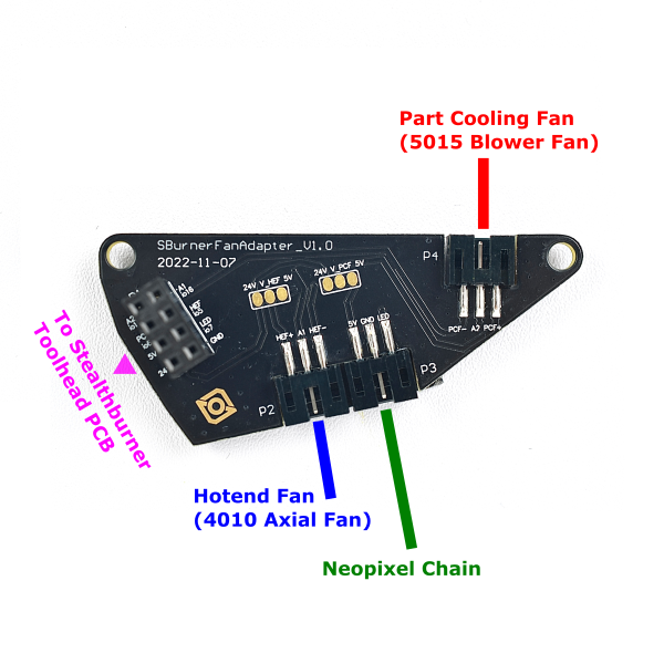
The fan adapter PCB attaches to the rear of the StealthBurner main body. Use two M3x10 FHCS screws to install the PCB directly on the back of the 5015 fan.
- Connect the 5015 Blower Fan to the port P4. If you are using your own fan, use the polarity labelled on the PCB to crimp a 3pin JST-PH2.0 connector to your fan cable.
- Connect the 4010 Axial Fan to the port P2. If you are using your own fan, use the polarity labelled on the PCB to crimp a 3pin JST-PH2.0 connector to your fan cable.
- Connect the Neopixel Chain to the port P3.
- The 2x4 headers on the two PCBs connect to each other when your install the Stealthburner main body to the rest of the toolhead - this allows you to easily attach and detach the StealthBurner when performing maintenance or upgrades. Make sure the two headers line up properly each time they are connected.
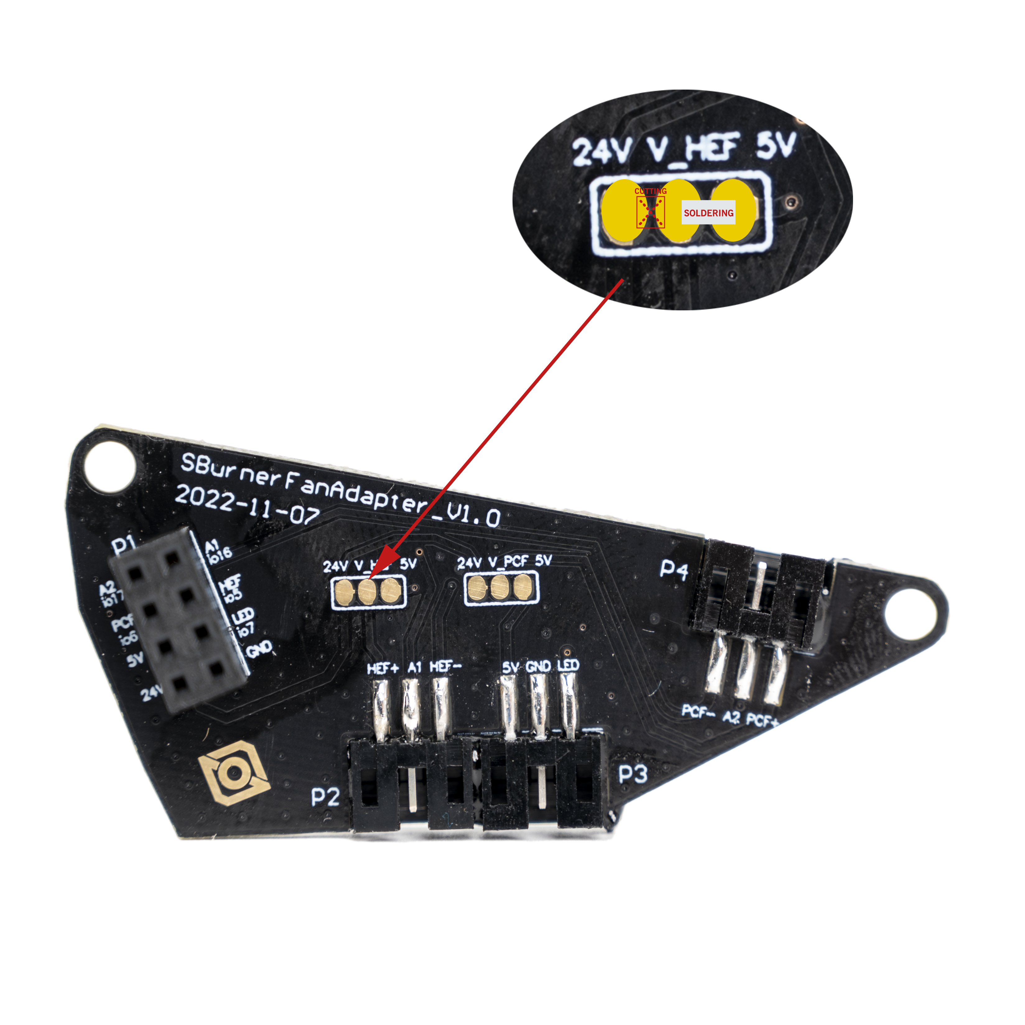
Note: When selecting 5V power supply, refer to the diagram:
Cut the trace between 24V and HEF. Solder a bridge between HEF and 5V. (Same applies to PCF operation.)
¶ Assembling the Nozzle Probe
Our nozzle probe is slightly different from the official endstop, use our printed part.
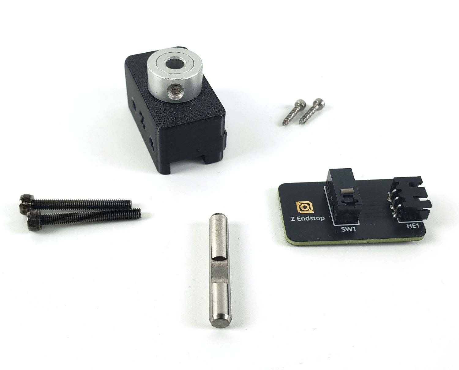
Use two M2x10 self tapping screws to install the PCB onto the printed part. The screws go through the two holes on the D2F switch and fasten sideways into the printed part.
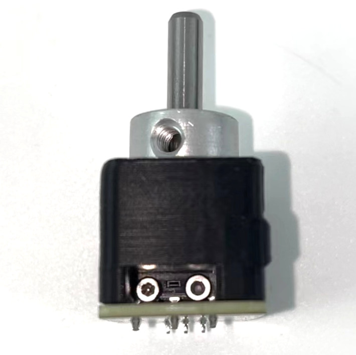
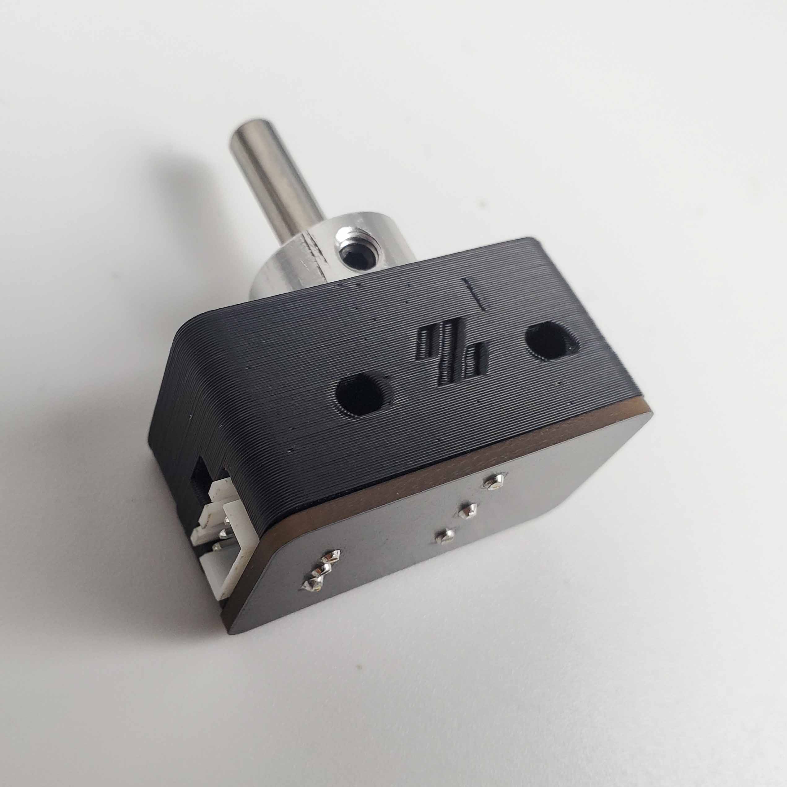
The final result looks like this. Use two M3x25 SHCS to mount the nozzle probe onto the printer. Remember to install one set screw into the pulley, but do not overtighten it. The screw screw is there to ensure that the shaft cannot fall out of the probe body; however it should not be so tight as to impede the shaft from freely moving up and down.
¶ Wiring the Bed Heater
Starting from Rev.C, our build plates have been updated with our in-house heatpad design. The new design uses screws to mechanically secure the heatpad as a failsafe. In addition, the bed sensor utilizes the more reliable ATC Semitec 104NT-4-R025H42G thermistor as the temperature sensor. Furthermore, the bed wiring harness now utilizes a breakout design - so that the build plate can be conveniently detached entirely from the top side of the deck panel.
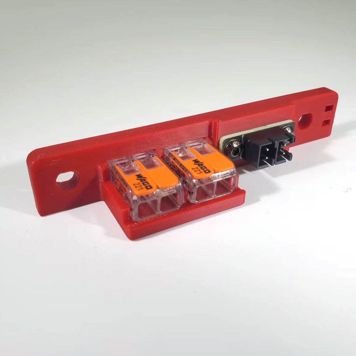
Start by assembling the bed WAGO mount. The printed part can found here. Use two heat set inserts from the front of the printed part this will be used for mounting the 2x2 XH Splicer PCB. The two WAGO terminals are snapped into the printed part directly. Each WAGO terminal will be used to breakout a bed power line. The 2x2 XH Splicer PCB is fastened using two M3x6 BHCS screws. You need to install M3x5x4 heatset inserts before fastening the screws. The splicer PCB will be used to breakout the bed thermistor. Finally the completed bed WAGO mount will be installed onto the printer using two M5x10 BHCS screws.
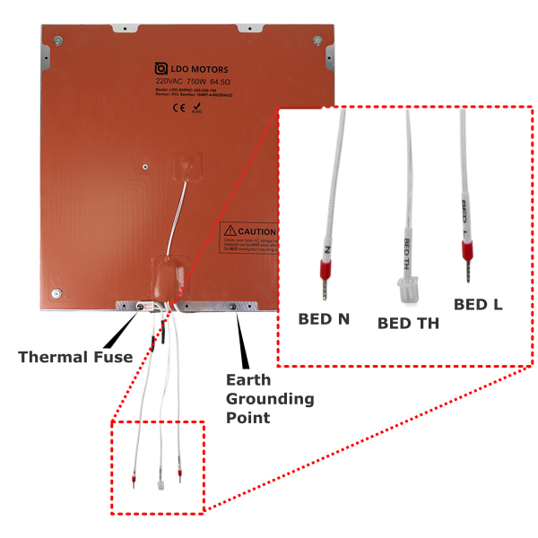
Before we start wiring, let's first take a look at the build plate assembly. There are three cables that are directly attached to the bed heater. The two thick braided cables are the bed power lines (labelled N and Bed L). The thinner two pin cable is the bed thermistor (labelled BED TH). Finally there is a M4 screw and serrated washer directly fastened to the aluminum plate - this is where you attach the bed PE (protective earth) cable to ground the build plate.
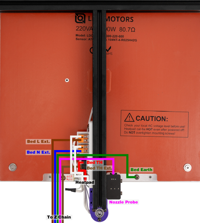
Shown below is the overall wiring layout for the build plate. Also shown is the wiring for the Z endstop (nozzle probe).
¶ Wiring the XY endstop
The XY endstop cable has a 4pin JST-XH connector on one end, and on the other end there are two 3pin JST-XH connectors, one labelled X Stop and one labelled Y Stop.
¶ Routing the LED strips
Our kit includes two LED strips to install as ceiling lighting for your printer. Please remember to mount using the printed part to prevent a short with the extrusion and mount using M3 hammerhead nuts (or t-nuts) and M3x8 SHCS screws.
Print the bar clips from the print guide and mount them at the top left and right extrusions. We recommend following the routing path shown in the diagram below or route thru the Z-motor A opening:
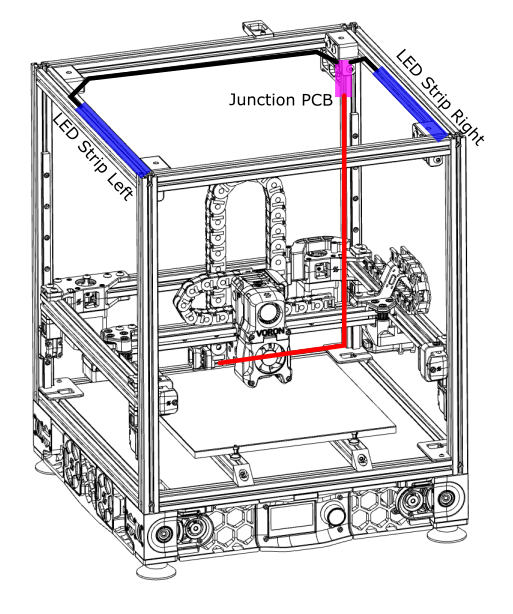
Remember to cover the slots where your LED cables are routed with the extrusion covers provided with the kit.

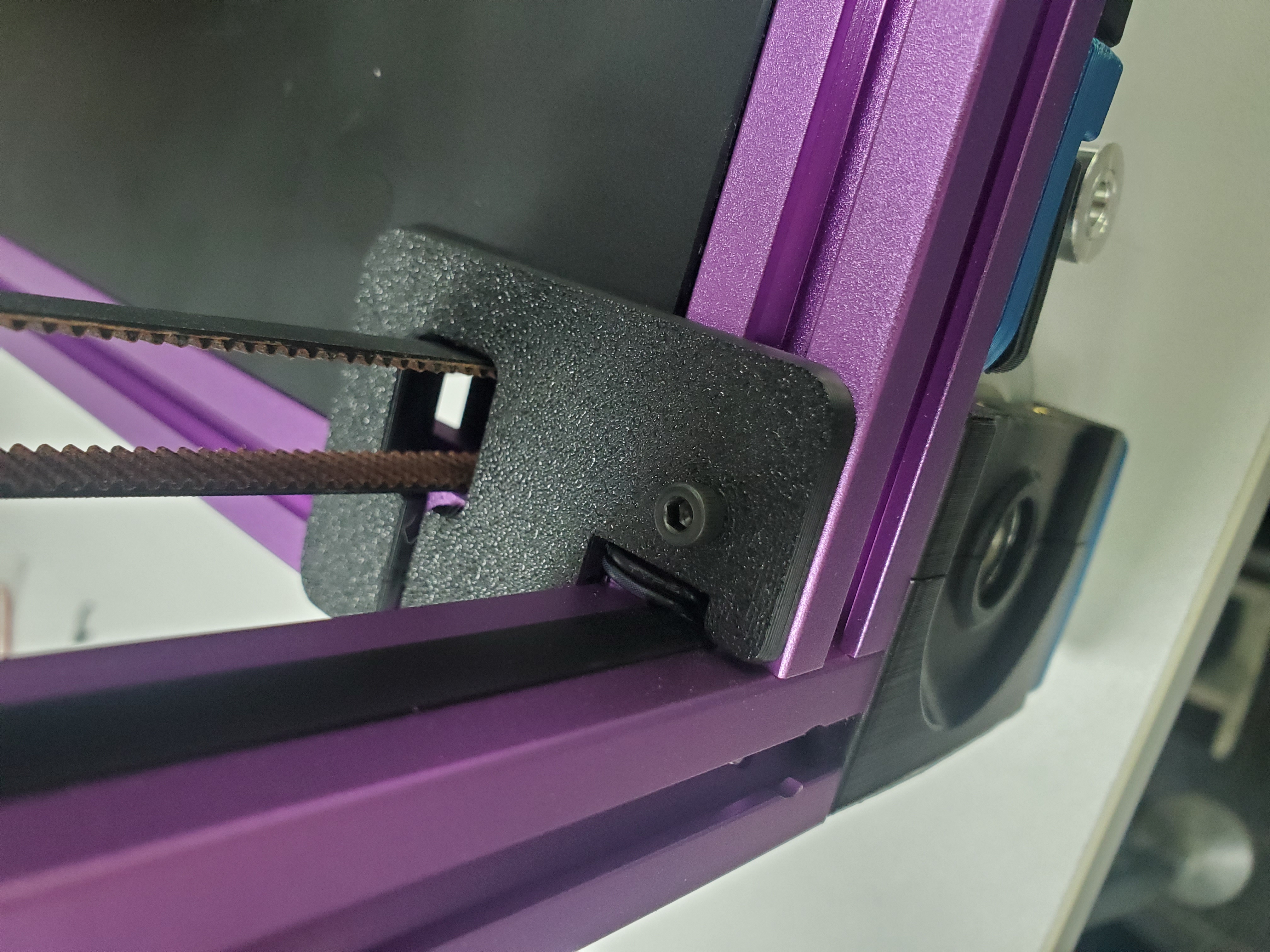
Use the modified Z-motor cover A (link in Printed Parts Guide) if you choose to route the wiring through that opening.
¶ Below Deck Wiring
¶ Preparing the Inlet
Your kit should include a pre-wired AC inlet. Double check that the wiring is correct, the final layout should be as follows:
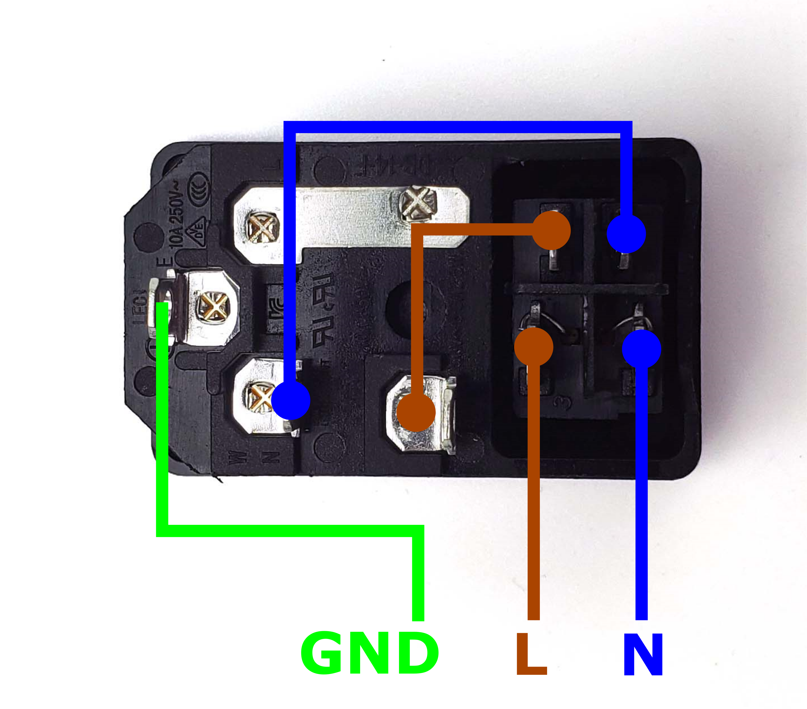
Take the inlet cable included in the kit and attach the wires using the above layout as reference. When wired correctly, your live wire will be protected by a fuse, and the switch on the front side of the inlet will operate correctly (lights up when turned on).
¶ Preparing the Power Supply Unit
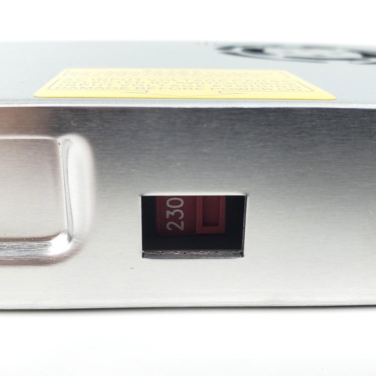
The 24V power supply unit that comes with the kit contains a switch on the side to select between 120V and 230V. Flick the switch to the correct value* before powering it on! Failing to do so can destroy the power supply!
* EU Customers may receive the Meanwell RSP-200-24 to comply with local regulations. This power supply features power factor correction and has a universal AC input range, so no switching is needed.
¶ Preparing the Mainboard (LDO Voron Leviathan Board)
Let's prepare our mainboard before proceeding with further wiring:
- We need a Leviathan Bracket Left and Leviathan Bracket Right and two Din Clips which are included in our kit. These will allow your mainboard to be clipped onto DIN rails later.
- Refer to this guide LDO VORON Leviathan V1.2 to prepare your Leviathan Board.
¶ Installing the DIN Rails
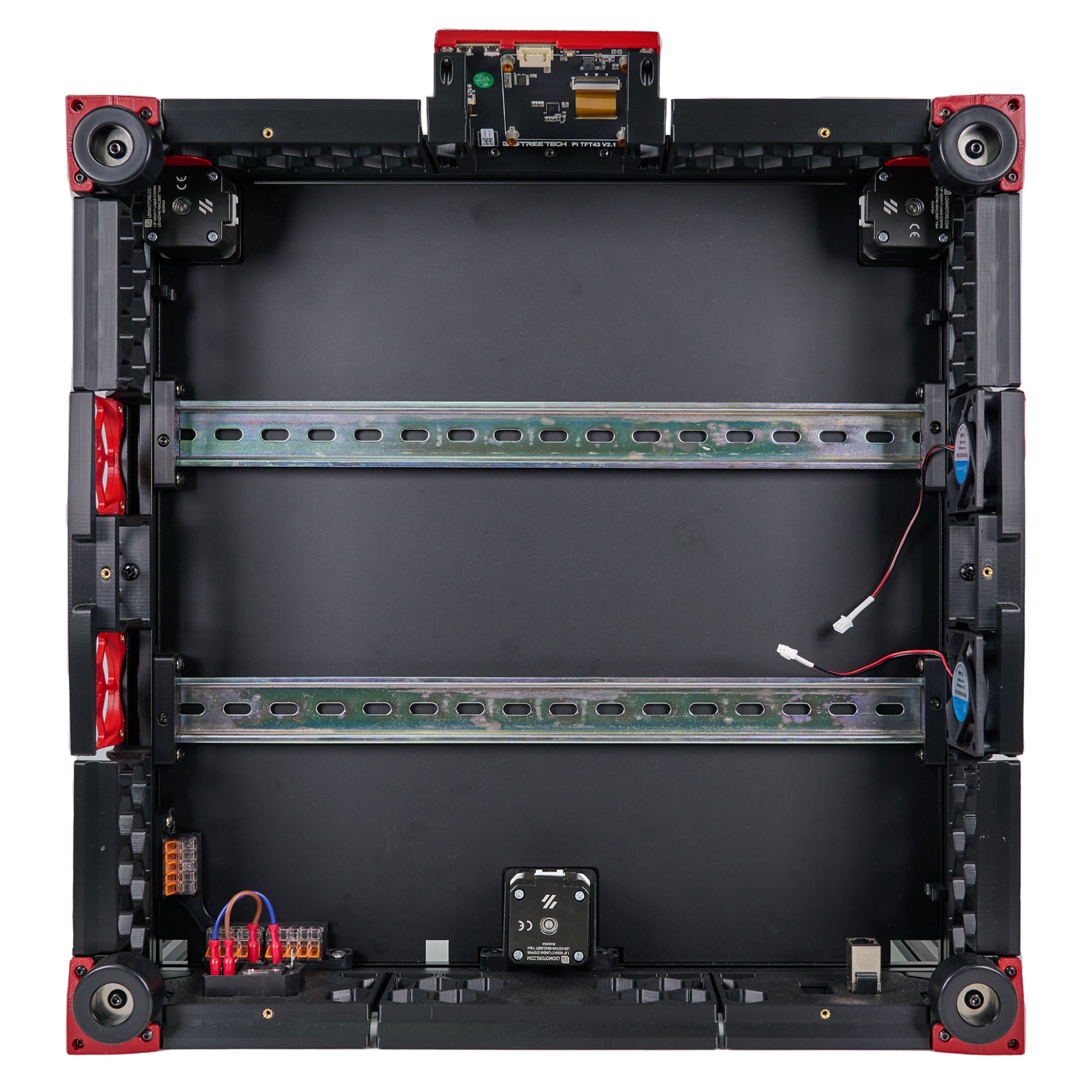
These DIN rails run from left to right. Don't forget to install the plastic end caps on each of the DIN rails.
¶ General Placement
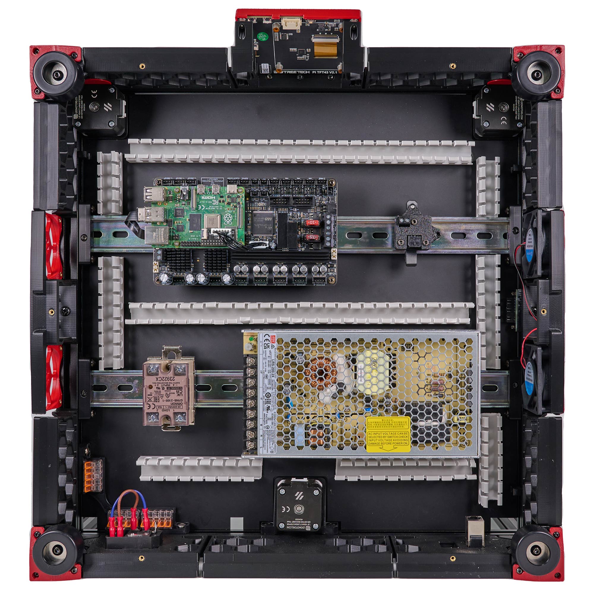
In this step, we will place the electronic components and wire ducts as shown in the picture below. The positioning of the components is not as critical, as they can be adjusted as needed later on.
Use VHB tape to stick these wire ducts on the deck panel.
¶ Connecting Steppers
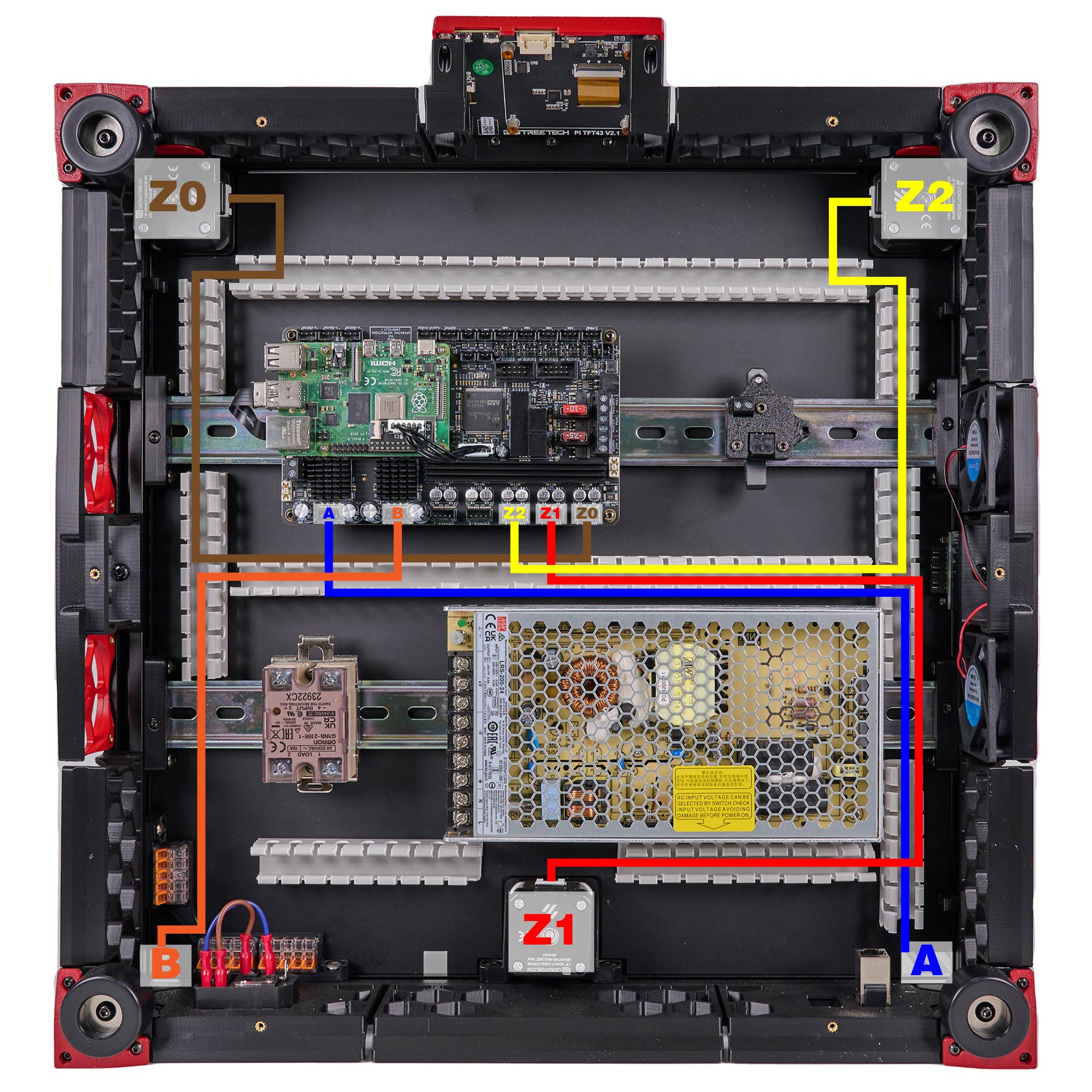
In this step, we will install all the stepper motor cables (except for the E motor). We recommend taking advantage of the included cable tags to label your stepper cables. Follow the table and diagram below:
| Stepper Motor | Physical Position* | Controller Position |
| A | Rear Right of Gantry | HV-STEPPER-1 |
| B | Rear Left of Gantry | HV-STEPPER-0 |
| Z0 | Front Left | STEPPER-0 |
| Z1 | Rear | STEPPER-1 |
| Z2 | Front Right | STEPPER-2 |
| <NOT USED> | <NOT USED> | STEPPER-3 |
| <NOT USED> | <NOT USED> | STEPPER-4 |
*All positions are specified as if standing in front of an upright printer and looking towards it.
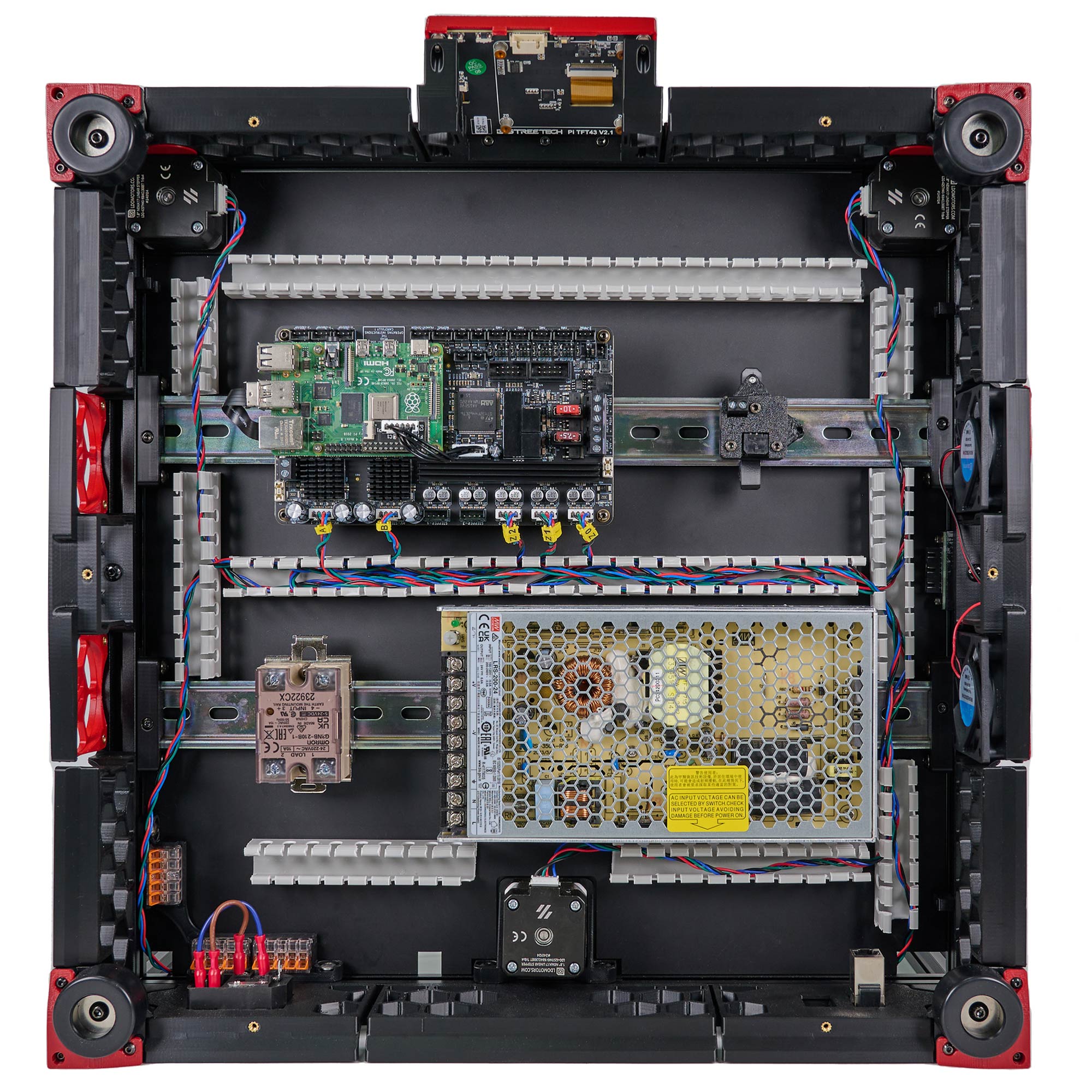
The end result should look like this:
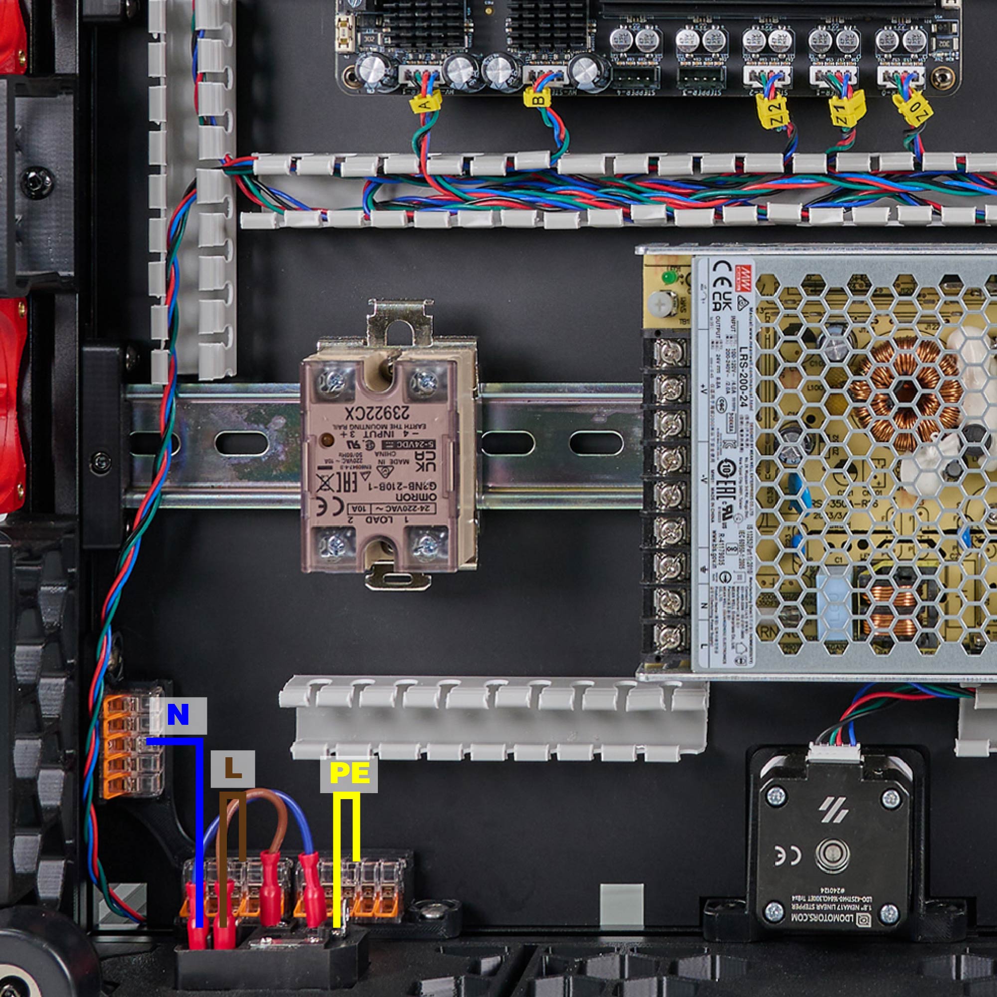
¶ Connecting Inlet and WAGO
In this step we will connect the AC Inlet and the Wago terminals. Follow the following diagram:
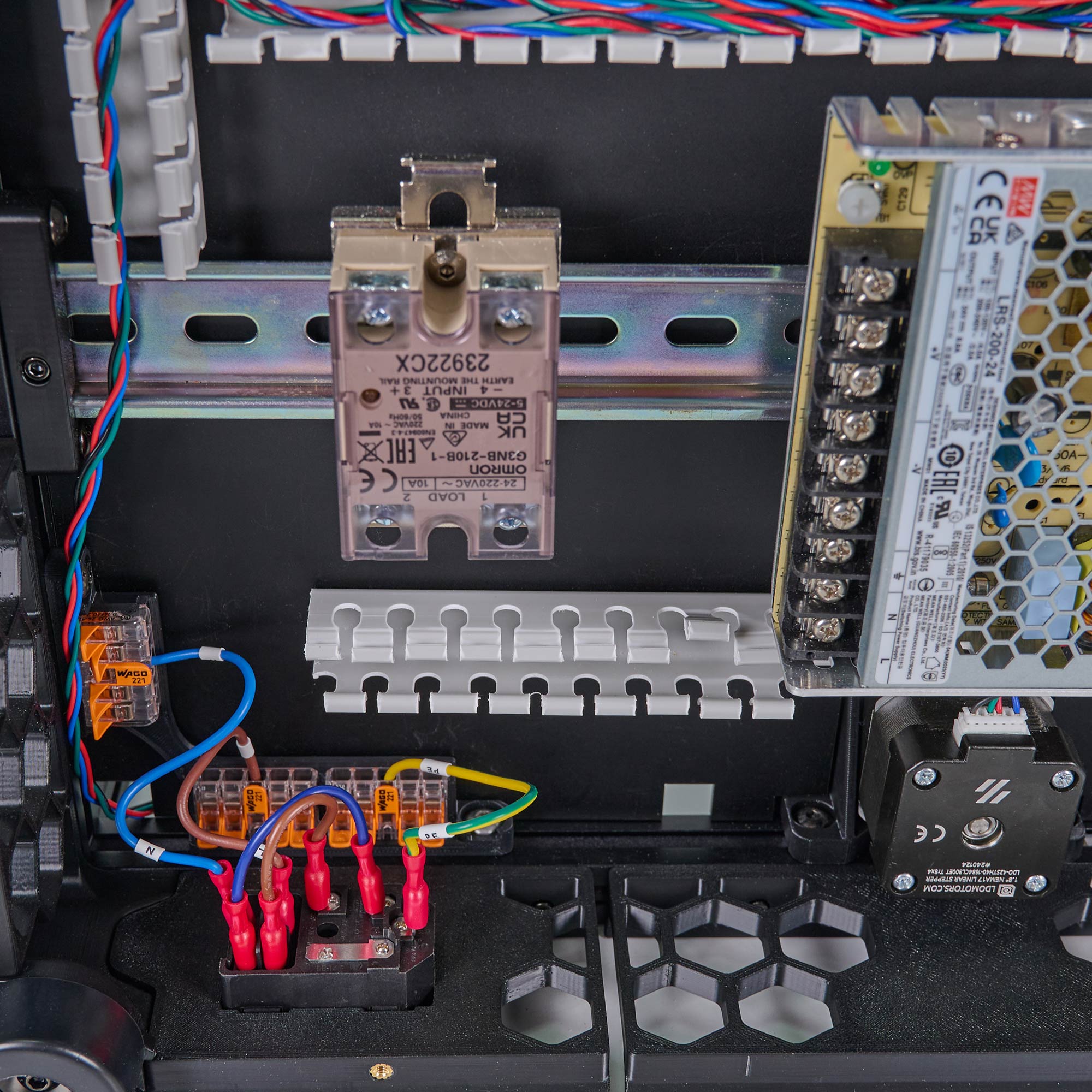
The end result should look like the following:
¶ Connecting Wago and PSU
In this step we will connect the Wago terminals and 24V PSU. Follow the following diagram:
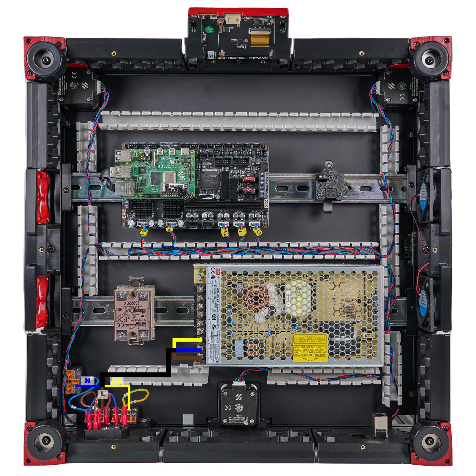
The end result should look like the following:
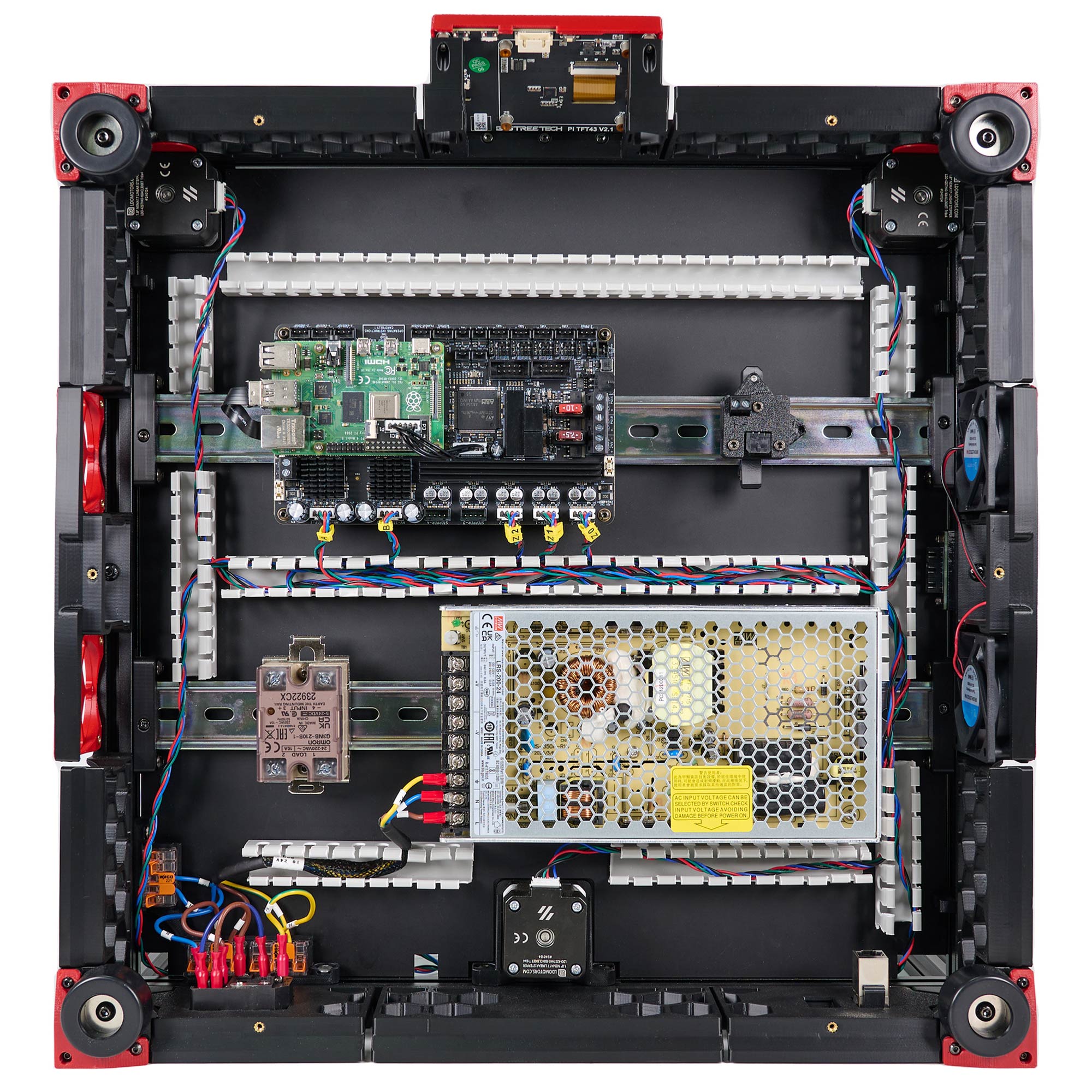
¶ Checkpoint #1
Before moving on to the next step, let us check all the wiring so far. Incorrect wiring of AC/mains can be dangerous - therefore, always double check your work, and then triple check it once more:
- Remember to check everything without the power cable plugged into the inlet!
- Check that the blue, brown and yellow/green wires should go into their respective 5pin wago terminals.
- Use a multimeter to check continuity between all nodes of the same colour - they should be shorted.
- Use the multimeter to check continuity between Live, Neutral, Earth - they should not be shorted with each other.
- Check again that the power supply voltage input switch is set to the correct value: 115V vs 230V
- After checking all of the above, plug in the power cable and switch on the inlet: The power supply should turn on and it's LED should light up.
- Switch off the inlet and remove the plug, we can now move on to the next step.
¶ Connecting 24V
In this step, we will connect the power supply to the controller board and the relay.
- Connect the HV end of the HV to MB HV cable to the controller board and the TO MB HV end to the PSU. (If you want to use 48V power supply, please use the cable labeled 48V TO MB cable here.)
- Connect the SSR SIG end of the SSR to MB cable to INPUT 3&4 on the SSR. The red cable goes to INPUT 3 and the black cable goes to INPUT 4. Connect the To SSR end to the HEATBED terminals on the controller.
- Connect the To SSR end of the SSR to Wago cable to a brown wago slot and the other end to LOAD 2 on the SSR.
- Connect the 24V end of the 24V PSU to MB cable to the Board terminals on the controller and the TO MB end to the PSU.
- Connect the TO TOOLHEAD end of the 24V power cable to the PSU and the 24V IN end to the USB Adapter PCB.
- Pay attention to the polarities.
- The SSR connection is critical, an incorrect connection can cause catastrophic damage. Pay close attention to the numbers labelled on the SSR and position of the yellow LED light.
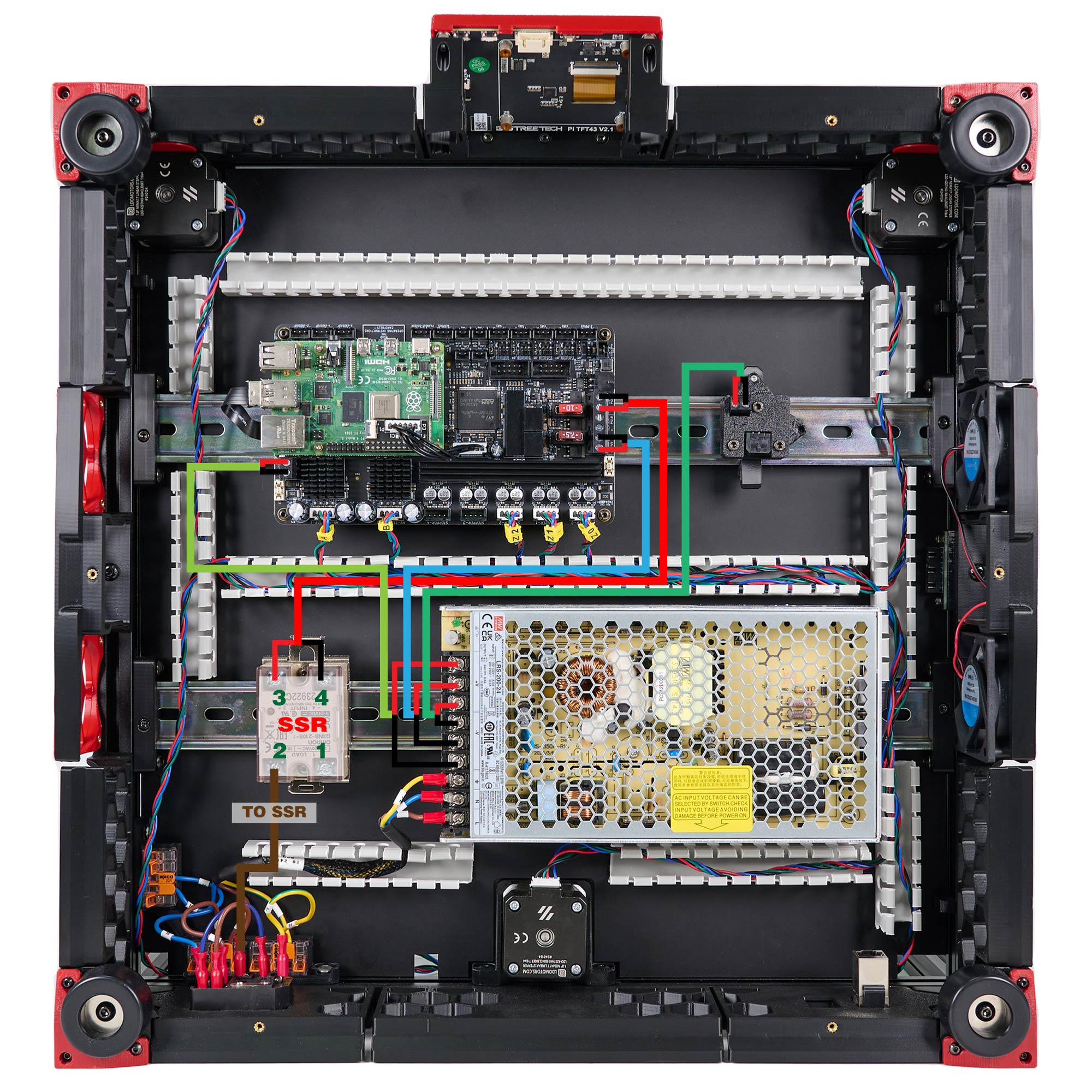
The result:
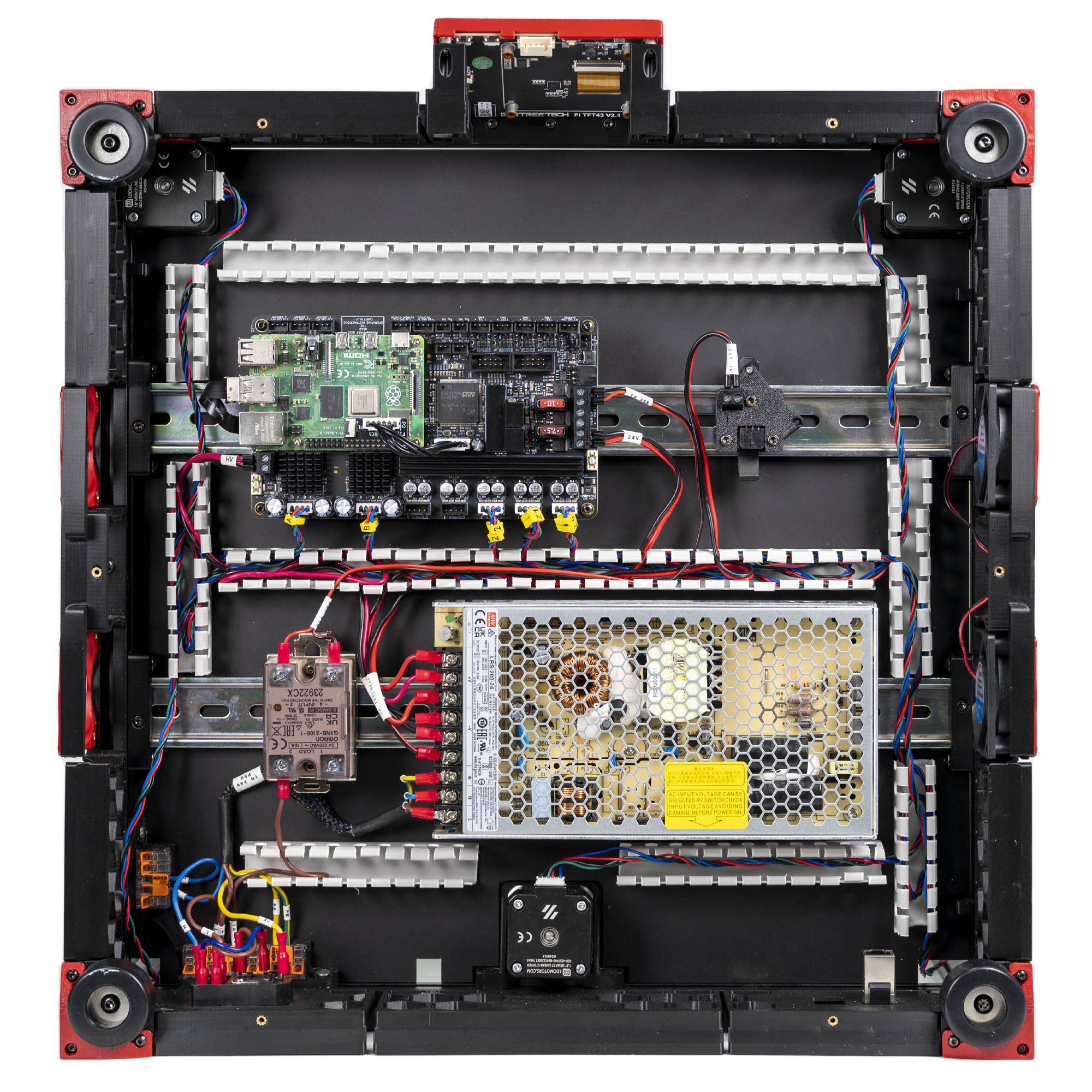
¶ Connecting Build Plate
In this step, we will make build plate connections.
- Connect the Bed N end of the heatpad to a blue Wago terminal.
- Connect the Bed PE of the heatpad to a yellow Wago terminal.
- Connect the Bed L end of the heatpad to LOAD 1 on the SSR
- Connect the Bed TH end of the thermistor to TH1 port on the Leviathan board.
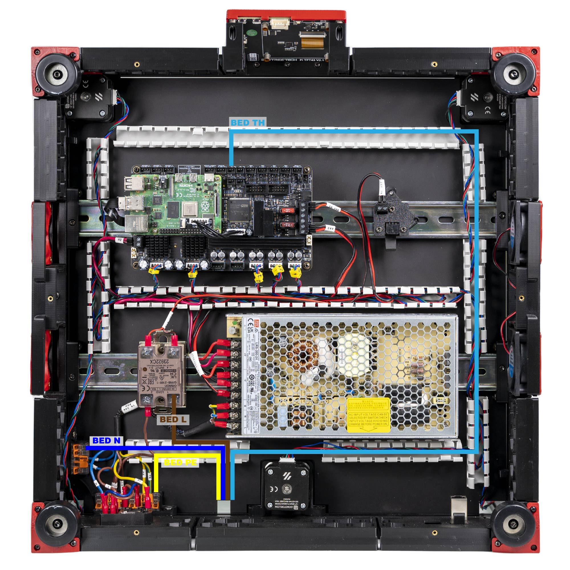
The overall result:
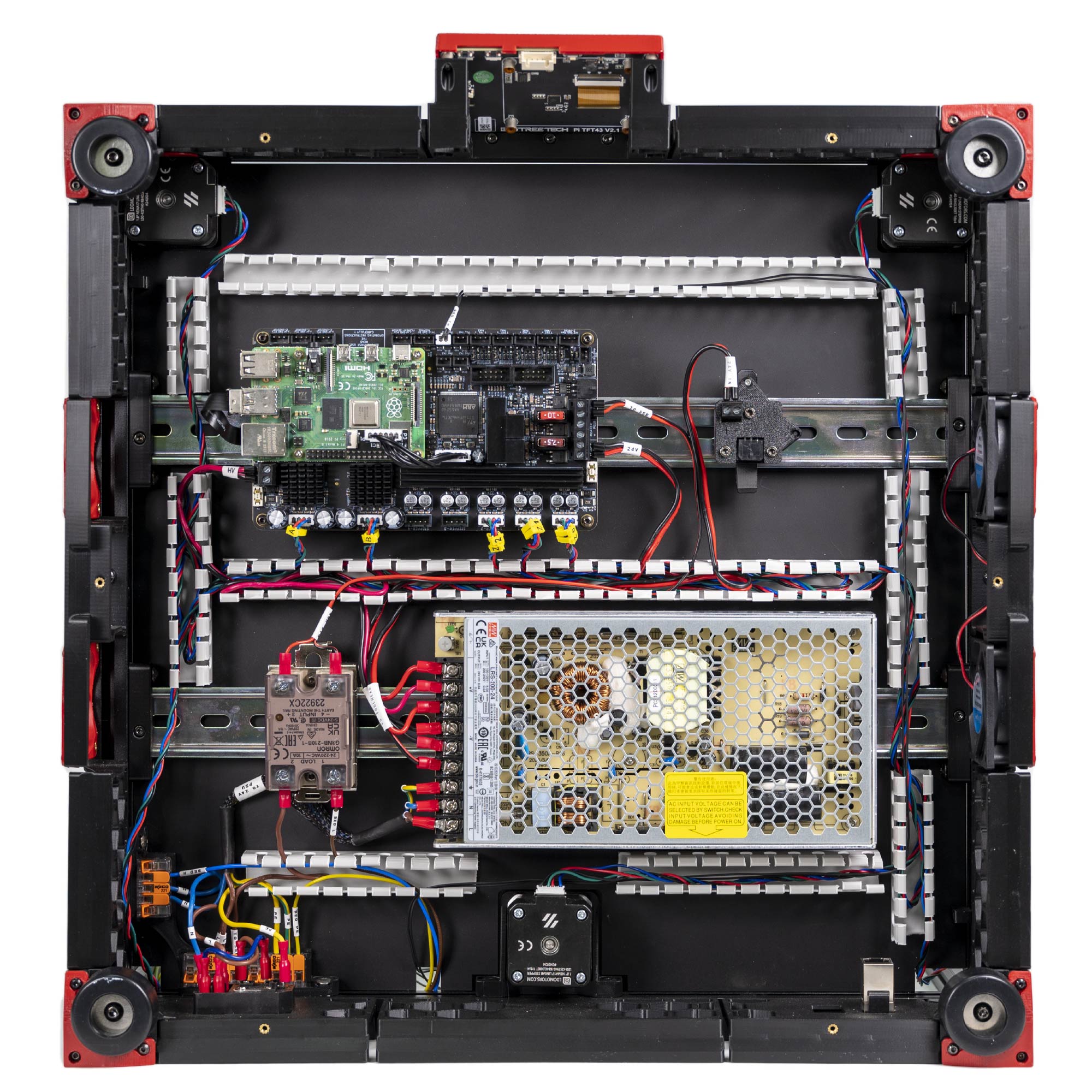
¶ Connecting the Toolhead Cables
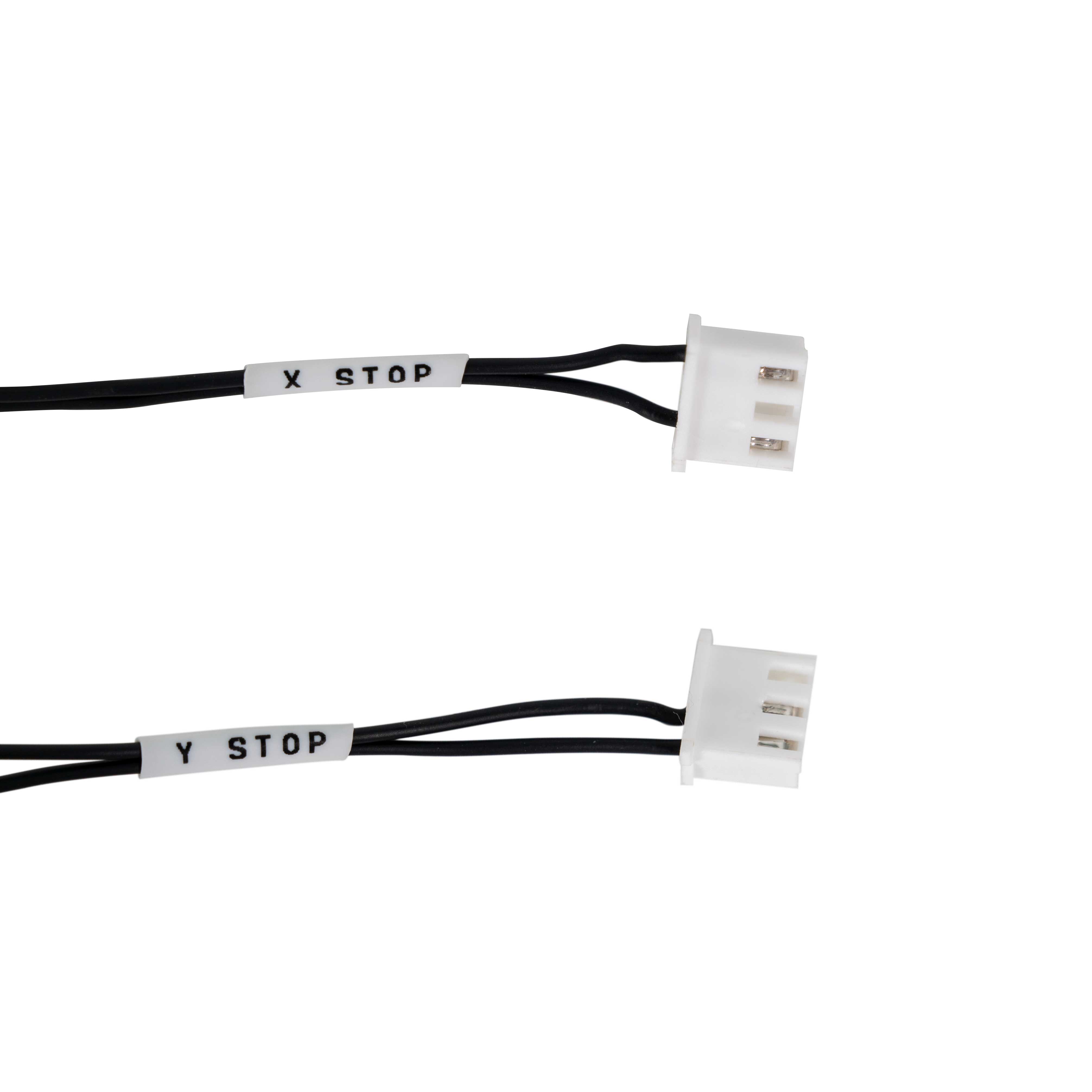
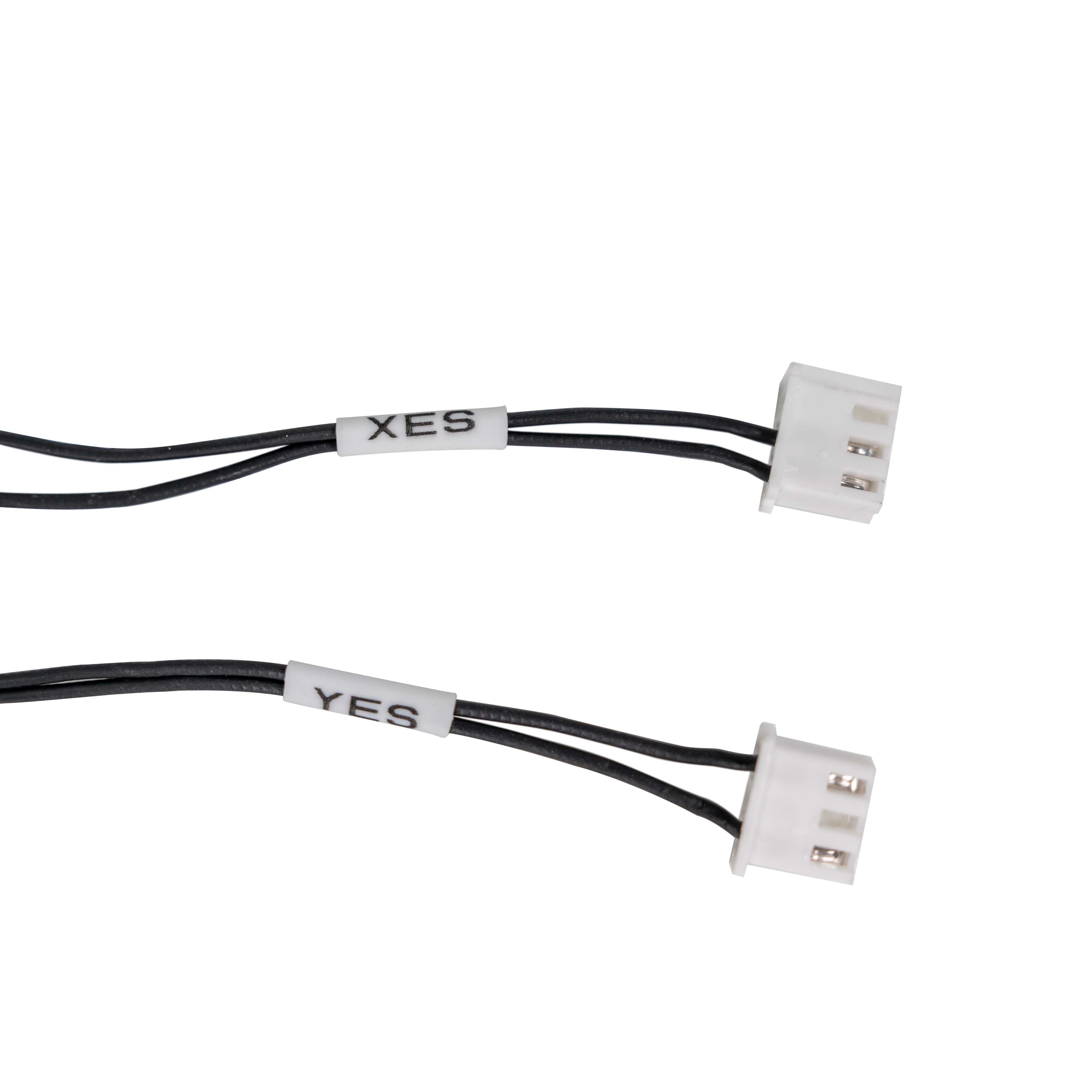
Before wiring, the first thing you need to do is identify whether you receive the incorrect XY endstop cables. If you receive the incorrect cables, please follow this guide to repin the wires.
- The incorrect cables come with labels as X Stop and Y Stop.
- The correct cables come with the lables as XES and YES.
|
|
In this step, we will connect the endstop cables to the Leviathan controller board and the toolhead cable.
- Connect the XY endstop cable to the 3 pin connectors (Labeled X-ENDSTOP/Y-ENDSTOP) on the board.
- Connect the Z endstop cable to the 3 pin connector (Labeled Z-ENDSTOP) on the board.
- Connect the toolhead cable to the USB Adapter PCB.
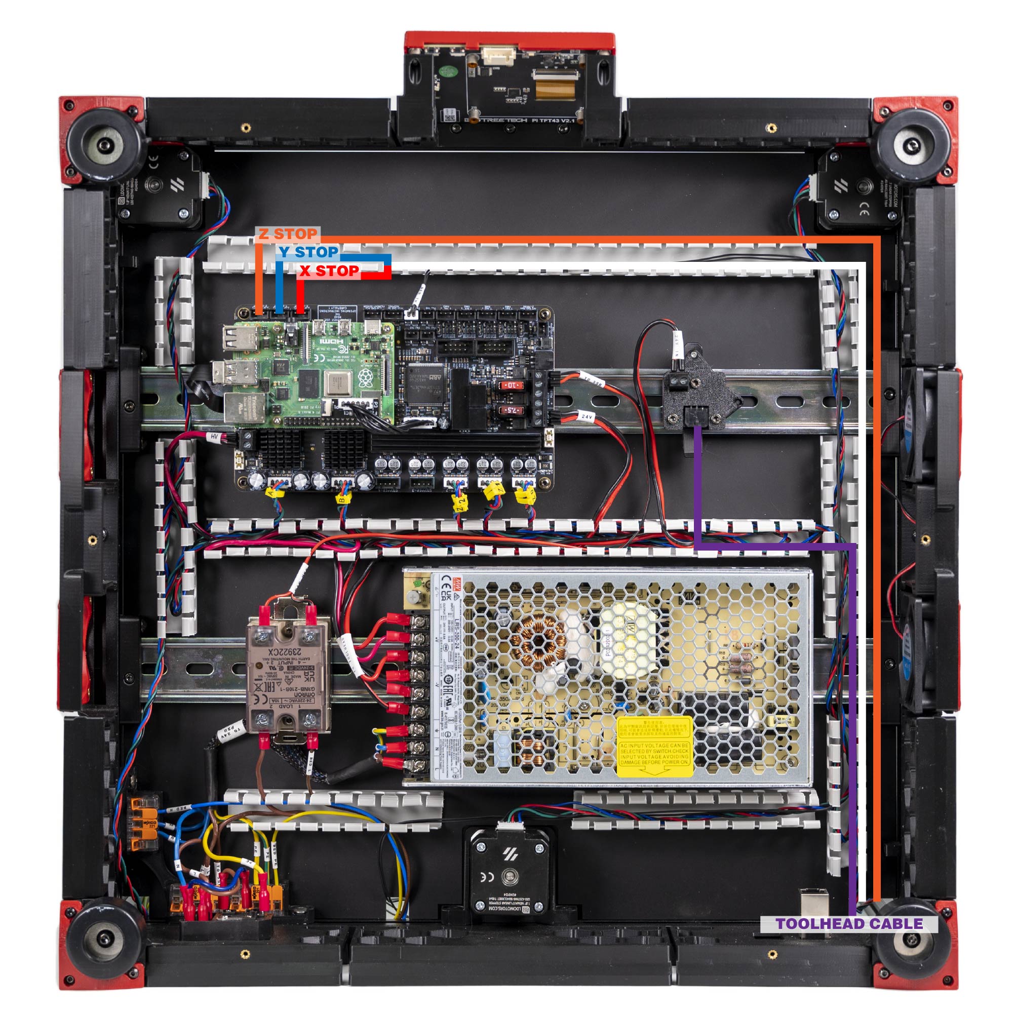
Here is the result:
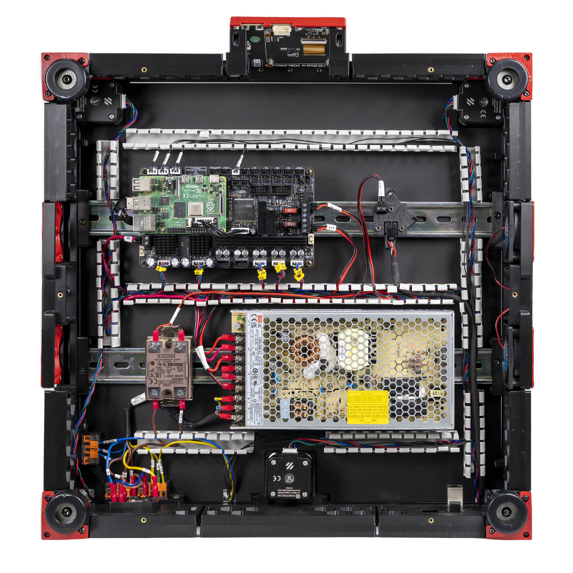
¶ Connecting the Fans and the LED Strip
In this step, we will connect the Fans.
- Remember that the two 6020 fans are joined using the 3x2 splicing PCB.
- Please remember to mount 3x2 splicing PCBs using the printed part to prevent a short with the extrusion.
- Connect the fans according to the following table
| Item | Cable Label | Controller Position |
| PCB Fan | PCB FAN | FAN2/PF7 |
| LED Strip | LED STRIP | LED-Strip/PE6 |
| Filter Fan | FILTER FAN | FAN3/PF9 |
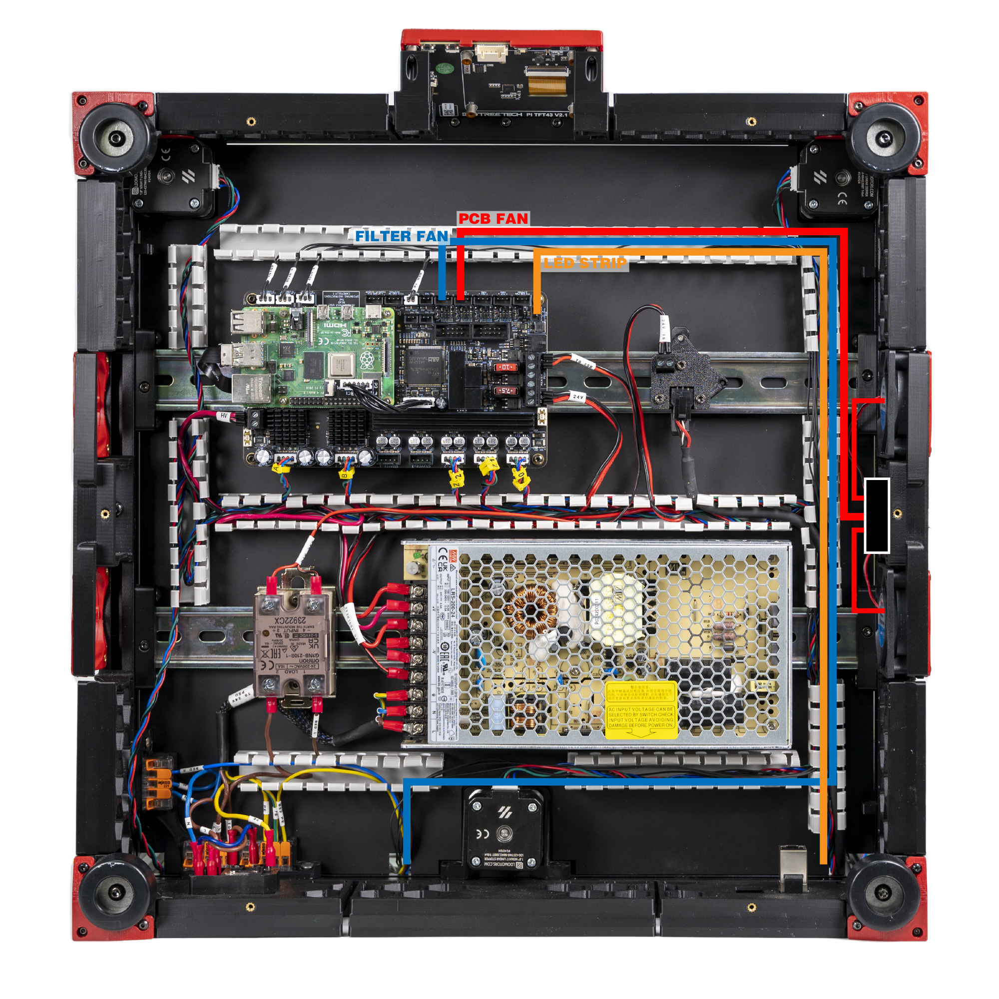
The result is below:
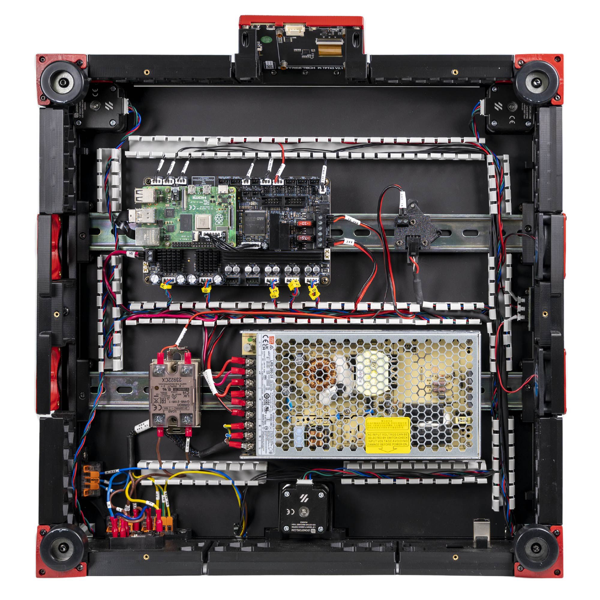
¶ Connecting the FFC Cable, Ethernet Cable, USB Cable and Fame PE
In this step, we will connect the remanining items.
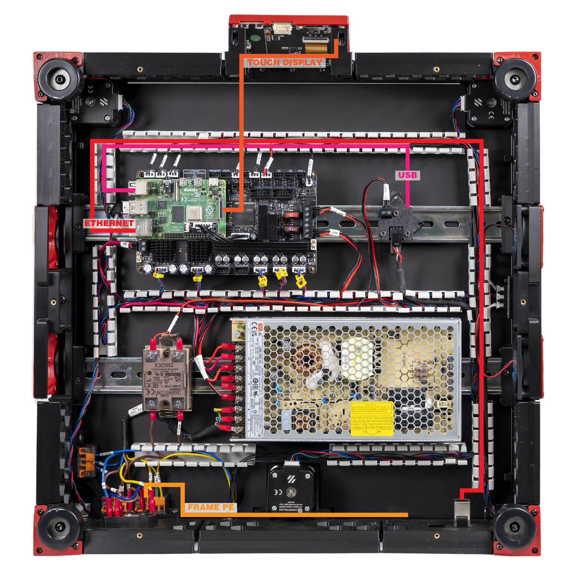
- Use the provided ribbon cable to connect the touch display to the Raspberry Pi. The ribbon cables need to be connected in a specific orientation - consult this photo and this photo (note the blue backing).
- User the provided ethernet cable to connect the rear ethernet jack to the Raspberry Pi.
- Connect the usb cable to the Raspberry Pi and the USB Adapter PCB.
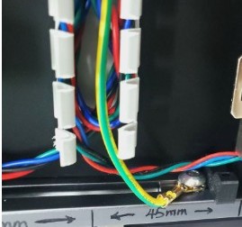
- Connect the FRAME PE end to a yellow Wago slot.
The grounding wire should be attached using the washers and screwed into the frame. This will ensure a secure electrical connection between earth and the printer frame (image just for reference):
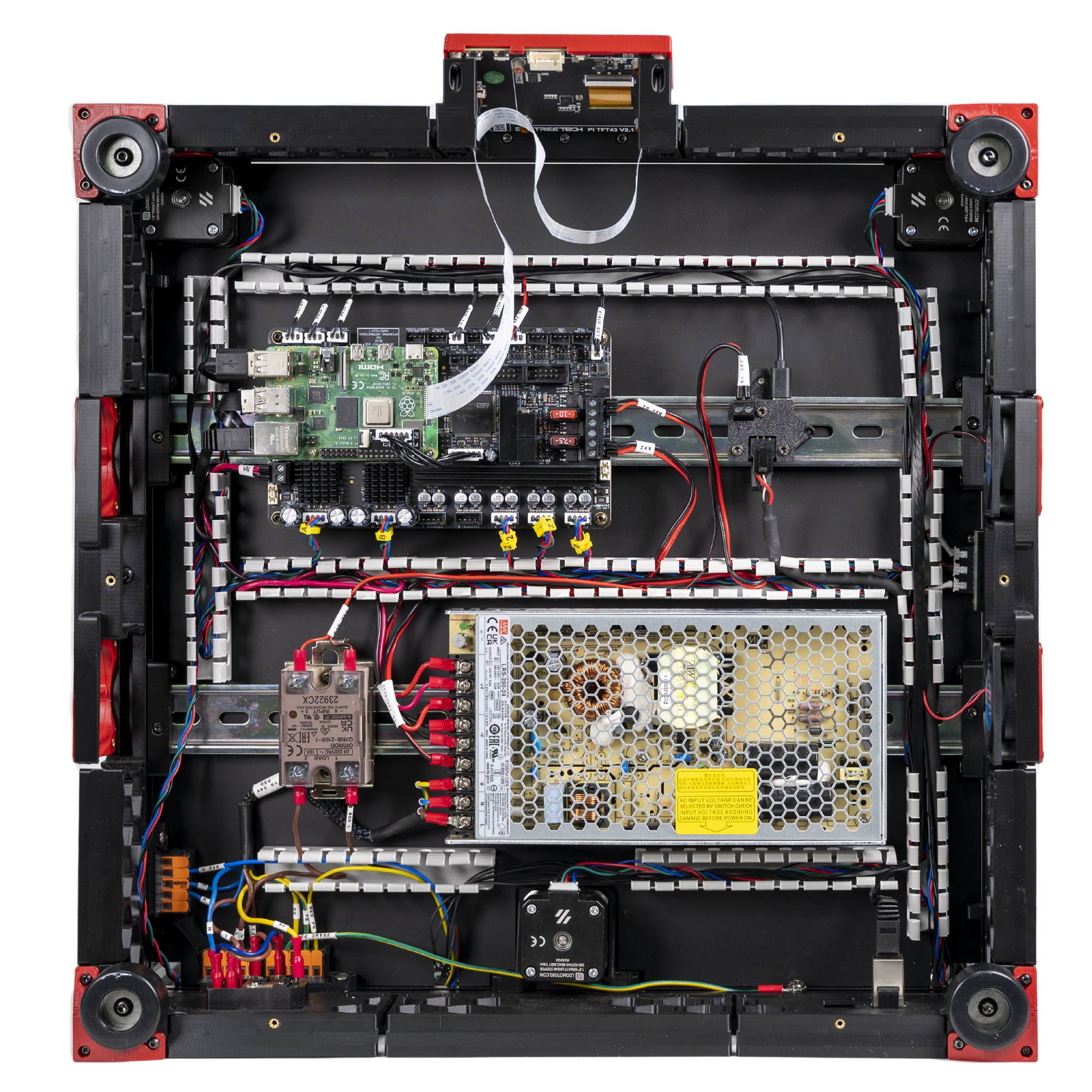
This is the result:
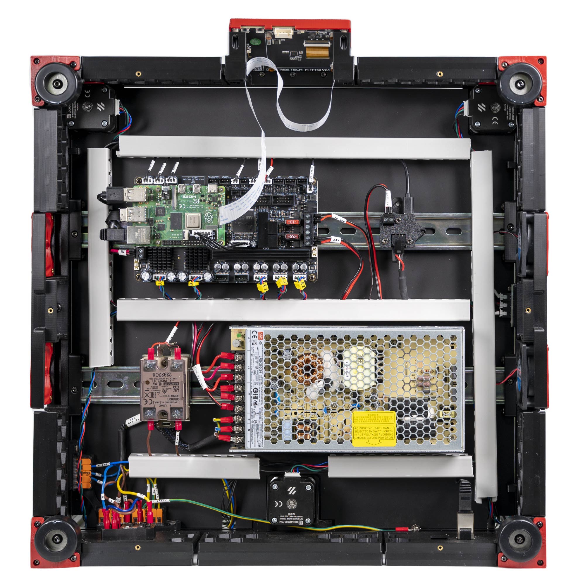
¶ Finish Line
Congratulations! You have completed all the wiring, all that is left now is to cover up the wire ducts! We've posted a high resolution image here for you to compare your work.
¶ Software Setup
Now that you have completed hardware wiring, it is time to move on to software setup. The following sections outline resources you can use to finish setting up software for your printer. Many of the instructions below are derived from the official Voron documentation site which you can visit here.
¶ Raspberry Pi OS Setup
We first need to install an operating system onto your Raspberry Pi. The easiest way to do this is to use their official imager.
- Download and run the Raspberry Pi Imager.
- Under Advanced options, enable SSH, set a username and password, and enter your WIFI info.
- Under Operating System Choose Raspberry Pi OS (other) -> Raspberry Pi OS Lite (32bit).
- Insert the SD card provided in the kit and choose it under storage. Click Write and wait for the Imager to finish writing the data into the SD card.
- Remove the SD card from your computer and insert it into the Raspberry Pi
¶ Remotely Accessing Your Raspberry Pi via SSH
Many of the following steps below require you to remotely run commands on your Raspberry Pi via SSH. If you are on Windows, putty is the goto tool. If you are on Mac OS, you can simply run ssh on your Terminal. For more info about remotely accessing your Raspberry Pi using SSH, read this article.
¶ Klipper and Web Interface Setup
On your Raspberry Pi, you will need to install Raspberry Pi OS Lite, Klipper, and a web interface to manage your printer. The most popular options for a web interface are Fluidd and Mainsail - both are great options with similar controls, you can't go wrong picking either of them. To make installation a breeze, we recommend using KIAUH, which is a script that helps you install Klipper, Fluidd/Mainsail and any other dependancies that may be required.
- Follow the instructions on the KIAUH github page.
- Use KIAUH to install Klipper, then Moonraker, then Fluidd or Mainsail, then KlipperScreen.
¶ Setting up the Touch Screen
If you followed the previous step with KIAUH, then KlipperScreen should be successfully installed. Read this guide for information on touchscreen setup and instructions for rotating screen orientation.
¶ Mainboard Firmware Setup
The Leviathan board is pre-programmed when you receive it.
If you need to update Klipper firmware, follow the instructions on the this site to install Klipper Firmware to the Leviathan board
¶ Determining the USB ID of your Mainboard and Toolboards
In this step we will obtain the USB ID of the Leviathan mainboard and Nitehawk toolboard. You will need these IDs in the next step when modifying your printer.cfg. Refer to this guide for different methods of obtaining the USB ID.
Since our printer consists of two boards (Leviathan mainboard and Nitehawk), we will need to correctly match up the USB ID to each board.
- The Nitehawk uses an RP2040 MCU, therefore its ID will be in a format similar to
usb-Klipper_rp2040_0123456789ABCDEF-if00. - The Leviathan uses an STM32F446 MCU, therefore its ID will be in a format similar to
usb-Klipper_stmf446xx_0123456789ABCDEF-if00.
¶ Klipper Configuration
With software and firmware both successfully installed. We can now move on to adding Klipper configuration files. These configuration files basically tell Klipper how our printer is wired. It also contains other useful data such as custom macros, tuning values, and so on.
- Open your printer's web interface by entering your Raspberry Pi's IP address in any browser. Initially, you will see an error message indicating a missing “printer.cfg” file.
- If you followed our wiring guide, you can use our pre-made configuration file. Download the configuration file and upload it via the Mainsail/Fluidd web interface. In Mainsail, go to Machine (Wrench icon). In Fluidd, goto Configuration ( {…} icon ). Both web interfaces allow you to upload by directly drag and drop the files onto the their webpage. Rename the configuration file to
printer.cfg. - Edit the printer.cfg file, under the
[mcu]section, replace{REPLACE WITH YOUR SERIAL}with the Leviathan MCU path you obtained in the previous steps.
¶ Initial Printer Setup and Tuning
With all the configuration files in place, you should now be able to use Fluidd/Mainsail to perform basic controls on your 3D printer. However, there are still a few more steps you should follow before starting your first print. Follow the initial startup guide on the Voron documentation site.